Introduction
You're holding a smartphone, driving a car, or working on a laptop right now. None of these devices would function without a PCB — short for Printed Circuit Board — embedded inside and doing the critical work of connecting every component together. From consumer gadgets to life-critical medical implants, these boards underpin virtually every electronic product made today. A defective PCB can render an entire assembly worthless, no matter how good every other part is.
This article explains what a PCB is, what it's made of, how it works, the main types available, and what separates a reliable board from a poor one. Whether you're an engineer selecting a manufacturer or simply curious about the technology inside your devices, this guide gives you a practical foundation for making informed decisions.
TLDR: Key Takeaways
- PCB stands for Printed Circuit Board—a flat board that mechanically supports and electrically connects electronic components
- Made from FR-4 fiberglass, copper traces, solder mask, and a silkscreen layer
- Electricity flows through copper pathways linking components like resistors, capacitors, and ICs
- Types span single-layer boards to multilayer and HDI designs for high-density applications
- Quality, layer count, and board type must match the application—no one-size-fits-all solution exists
What Is a PCB? Definition and Core Function
A Printed Circuit Board (PCB) is a laminated structure of conductive and non-conductive layers that mechanically supports electronic components and creates electrical connections between them. PCBs replaced the older method of wiring components point-to-point by hand, which was error-prone, inconsistent, and difficult to mass-produce.
The two core jobs of a PCB:
- Provide a rigid or flexible physical platform to mount components securely
- Carry electrical signals between components through etched copper pathways called traces
PCB vs. PCBA: Understanding the Difference
The bare PCB is just the board itself—substrate, copper traces, solder mask, and silkscreen. A PCBA (Printed Circuit Board Assembly) is the complete unit after all components (resistors, chips, capacitors, connectors) have been soldered onto it. The PCB is the foundation everything else depends on; the PCBA is the finished, functional product.
Historical Context: From Hand-Wiring to Mass Production
Austrian engineer Paul Eisler invented the modern PCB in 1943, filing a foundational patent for photographic printing and etching of copper foil. During World War II, the U.S. military mass-produced over 20 million proximity fuzes using ceramic PCBs, proving the technology's viability under extreme conditions.
The U.S. released the technology for commercial use in 1948, and mass adoption accelerated in the mid-1950s when Motorola introduced "plated circuits" in home radios.
Why PCBs replaced hand-wired construction:
- Cheaper to mass-produce with consistent quality
- Smaller and lighter than point-to-point wiring
- Enable automated assembly, reducing labor costs
- More reliable with fewer connection failures
Those manufacturing advantages have only compounded over time. The global PCB market is projected to reach $127.41 billion by 2031, fueled by AI servers, 5G infrastructure, electric vehicles, and medical devices. The quality of the PCB at the core of any product directly determines its reliability, longevity, and performance in the field.
What Is a PCB Made Of? Layers and Materials Explained
A PCB is a layered "sandwich"—every board, regardless of complexity, is built from the same core layer types: substrate, copper, solder mask, and silkscreen.
Substrate (Base Layer)
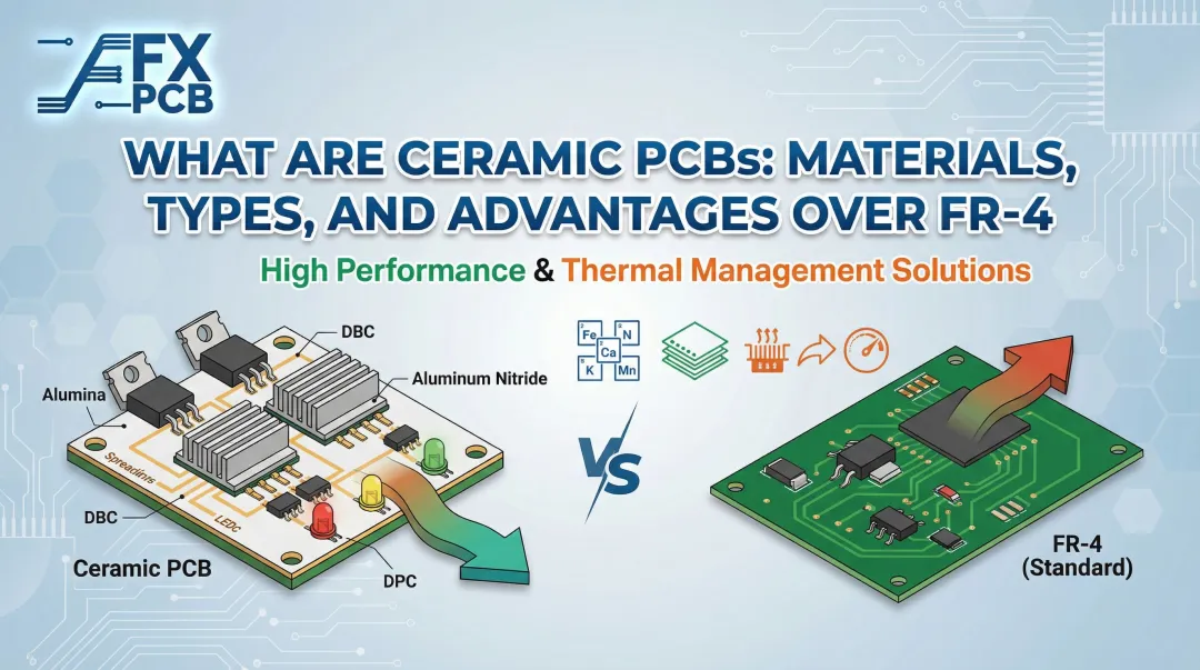
The substrate is the non-conductive core that gives the board structural rigidity. FR-4 (woven fiberglass reinforced with epoxy resin) is the industry standard, offering solid electrical insulation, low moisture absorption (0.12%), and a fire-retardant rating (UL 94 V-0).
FR-4 stays stable up to its glass transition temperature (Tg) — typically 130–140°C for standard grades, and 170–190°C for high-Tg variants used in automotive and industrial applications.
For flexible circuits, polyimide (PI) is the primary substrate, offering superior dynamic flexibility and high-temperature survival (360–410°C). Polyimide allows the board to bend without breaking, making it ideal for wearables, cameras, and medical devices.
SFX PCB manufactures boards across both material families — standard FR-4, high-Tg FR-4 (Tg170, Tg180), and polyimide substrates for flexible and rigid-flex designs.
Copper Layer (Conductive Layer)
Thin copper foil laminated onto the substrate carries electrical current. During manufacturing, unwanted copper is chemically etched away, leaving behind the circuit "traces" — the equivalent of wires printed flat onto the board.
Copper thickness is specified in ounces per square foot (oz/ft²):
- 1 oz/ft² (35 µm / 1.37 mils): Industry default for standard layers
- 2 oz/ft² (70 µm / 2.74 mils): Used for power circuits requiring higher current capacity
- 3+ oz/ft²: Heavy copper for high-current applications like motor drives, EV battery management, and power supplies
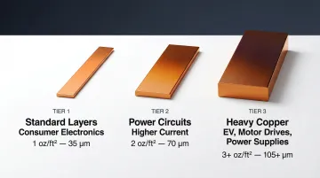
SFX PCB supports copper weights from 1 oz to 20 oz, covering everything from consumer electronics to industrial power systems.
Solder Mask and Silkscreen
The solder mask is a non-conductive polymer coating applied over the copper layer to:
- Protect traces from corrosion and environmental damage
- Prevent solder bridges between pads during assembly
- Give the board its characteristic color (green is standard, though blue, red, black, and white are also common)
The silkscreen is the printed text and symbols on top of the board that identify components, test points, polarity markers, and orientation guides for assembly technicians. White epoxy ink is most common, printed directly over the solder mask.
How Does a PCB Work?
A PCB works by providing a network of copper traces that act as precisely defined wires, connecting the leads or pads of each component. When power is applied, current flows through these traces in a controlled path. Each component then does its job: switching signals, amplifying current, storing charge, filtering noise, or processing data.
Key Components and Their Roles
Common components found on a PCB:
- Resistors limit current flow and divide voltages
- Capacitors store and release electrical charge, filtering signals and stabilizing power
- Transistors switch or amplify signals — the building blocks of logic circuits
- Diodes allow current in one direction only, protecting against reverse polarity
- Inductors store energy in a magnetic field to filter noise and manage power
- Integrated Circuits (ICs) pack thousands or millions of these elements onto a single chip
Component Attachment Methods
Two primary methods are used to attach components to a PCB.
Through-Hole Technology (THT) feeds component leads through drilled holes, soldering them on the opposite side. It's the go-to for large or high-stress parts like connectors and power devices. According to IPC benchmarks, THT accounts for 15% of component placements in modern electronics.
Surface-Mount Technology (SMT) places and solders components directly onto pads on the board's surface. SMT now accounts for 85% of component placements, enabling smaller boards, higher density, and automated assembly. SMT components can reach 0.4mm × 0.2mm (01005 package) — the scale that makes modern smartphones possible.
How Vias Enable Multilayer Routing
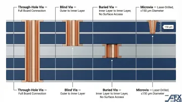
Vias are metal-lined holes drilled through the board that allow traces to jump between layers, enabling complex routing in multilayer boards. IPC-T-50N defines three main via types:
- Through-hole vias extend through the entire board thickness
- Blind vias connect an outer layer to an inner layer without passing completely through
- Buried vias connect inner layers only, with no surface access
Advanced designs also use microvias—laser-drilled blind structures with maximum diameter ≤150 µm (6 mils) and aspect ratio ≤1:1. Microvias are essential for High-Density Interconnect (HDI) boards in smartphones and wearables where component density demands it.
Types of PCBs: From Single-Layer to Flexible Boards
PCB Types by Layer Count
| Type | Layers | Typical Applications |
|---|---|---|
| Single-layer | 1 | Remote controls, LED lighting, basic power supplies |
| Double-layer | 2 | Automotive dashboards, LED drivers, consumer appliances |
| Multilayer | 4–16 | Industrial controls, automotive ECUs, computing, telecom |
| Advanced Multilayer | 16–50+ | High-speed servers, AI data centers, aerospace systems |
Practical manufacturing limits currently hover around 50–64 layers, though SFX PCB can fabricate up to 68 layers for applications requiring it.
HDI (High-Density Interconnect): IPC-2226 classifies HDI into Types I, II, and III based on microvia complexity:
- Type I: Single microvia layer on one or both sides
- Type II: Single microvia layer plus buried vias in the core
- Type III: Two or more microvia layers (stacked or staggered) with buried vias—essential for 0.4-0.5mm pitch BGAs
HDI boards achieve trace/space capabilities down to 50 µm (advanced) compared to 100 µm (standard), enabling extreme component density in smartphones, wearables, and medical implants.
PCB Types by Physical Form
Rigid: The standard flat, hard board made from FR-4 or other rigid substrates — the default choice for the vast majority of electronics where flexibility isn't a factor.
Flexible/Flex: Built on polyimide substrate that bends repeatedly without breaking. This makes flex PCBs well-suited for cameras, wearables, and medical devices where the board must conform to tight spaces or move in service. SFX PCB manufactures flex boards from single to 8 layers using polyimide or polyester substrates.
Rigid-Flex: Combines rigid and flexible sections in a single board, eliminating connectors and simplifying assembly. Common in aerospace, advanced medical equipment, and military hardware. SFX PCB produces rigid-flex designs with up to 20 total layers, including up to 12 dedicated flex layers.
Metal Core/IMS (Insulated Metal Substrate): Uses an aluminum or copper base to pull heat away from components. High-performance IMS materials reach dielectric thermal conductivities up to 7.5 W/m·K — nearly 19× higher than standard FR-4 (0.4 W/m·K). Used in LED lighting, power electronics, and EV battery management systems.
Choosing the right PCB type depends on:
- Operating environment (temperature, vibration, humidity)
- Available space and form factor constraints
- Signal speed and frequency requirements
- Current load and thermal management needs
- Production volume and cost targets
Getting the type right early avoids costly redesigns later. SFX PCB manufactures the full range — from standard 2-layer boards to advanced HDI, flex, and rigid-flex designs — so engineers can work with one qualified supplier across all board categories as a project scales.
Where Are PCBs Used? Key Industries and Applications
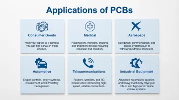
PCBs are foundational to virtually every industry that relies on electronics. Here are the primary sectors and specific applications:
- Consumer Electronics — Smartphones, laptops, tablets, smart TVs, and wearables. These applications prioritize miniaturization and cost efficiency, typically using HDI or flexible PCBs.
- Automotive — Engine control units (ECUs), ADAS systems, EV battery management, infotainment, and LED lighting. Boards must survive temperature swings from -40°C to +125°C and continuous vibration.
- Medical Devices — Patient monitoring systems, diagnostic imaging, ECG machines, glucose meters, drug delivery systems, and surgical robotics. Medical PCBs must meet IPC Class 3 reliability standards where failure is not an option. SFX PCB holds ISO 13485 certification for this reason.
- Industrial Automation — PLCs, motor controllers, power inverters, and process control systems. These boards operate in environments with dust, moisture, and electrical noise — requiring robust design and conformal coating.
- Telecommunications — Base stations, routers, 5G infrastructure, and network switches. Telecom is one of the fastest-growing PCB segments at 5.37% CAGR, driven by 5G deployment and data center expansion.
- Aerospace/Defense — Avionics, radar, satellite electronics, secure communications, and guidance systems. Rigid-flex PCBs are common here due to their ability to withstand extreme temperatures, vibration, and radiation.
Critical Insight: Requirements Differ Dramatically by Industry
The biggest risk isn't picking the wrong board type — it's working with a manufacturer who doesn't understand your industry's requirements. A consumer device can tolerate design tradeoffs that would cause a medical implant or automotive ECU to fail catastrophically in the field. By the time a field failure surfaces, rework costs dwarf anything saved on the front end.
When evaluating PCB manufacturers, verify they hold certifications specific to your sector — ISO 13485 for medical, AEC-Q familiarity for automotive, IPC-A-610 Class 3 for any safety-critical application. SFX PCB's multi-industry experience and certifications across ISO 9001, 14001, and 13485 mean engineers don't have to educate their manufacturer on what's at stake.
What Makes a High-Quality PCB?
Two boards can look identical on the surface but differ enormously in subsurface reliability—especially under thermal cycling or mechanical stress. Quality separates a reliable PCB from a problematic one.
Core Quality Factors
Five factors drive the gap between boards that hold up in the field and those that fail early:
- Trace tolerances — High-quality manufacturers maintain ±0.05mm precision, preventing signal integrity issues, crosstalk, and shorts.
- Laminate grade — Premium laminates like high-Tg FR-4 deliver better thermal stability and lower moisture absorption than bargain-grade alternatives.
- Copper adhesion — Poor adhesion causes trace lifting during thermal cycling. Controlled surface preparation and lamination processes prevent this.
- Via plating uniformity — Uniform, complete plating prevents open circuits. X-ray inspection is the only reliable way to detect hidden voids in via barrels and BGA joints.
- IPC conformance — Industry standards define minimum acceptable quality levels for each application class.
Key Quality Standards and Tests
IPC-A-610 Classes:
IPC-A-610 defines three distinct quality classes based on end-use requirements:
- Class 1 (General Electronic Products): Function is primary; cosmetic flaws acceptable if assembly works
- Class 2 (Dedicated Service): Extended life required; uninterrupted service desired but not critical (computers, appliances)
- Class 3 (High-Performance/High-Reliability): Performance on demand critical; equipment downtime cannot be tolerated (aerospace, medical, military)
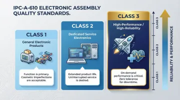
SFX PCB manufactures to IPC-A-610 Class 2 as standard, with Class 3 available for high-reliability applications. Class 3 requires significantly stricter workmanship, increasing manufacturing cost but ensuring maximum reliability.
Four testing methods work together to verify board quality at each stage:
- 100% Electrical Testing — Every bare board must undergo continuity and isolation checks before assembly. This catches open circuits, shorts, and impedance issues before components are placed.
- Automated Optical Inspection (AOI) — Cameras scan for surface-visible defects: component misalignment, polarity errors, and gross solder joint issues.
- Automated X-Ray Inspection (AXI) — The only method that reaches hidden solder connections under BGAs and Chip Scale Packages, detecting internal voids, opens, and cold joints.
- DFM Review — Evaluates trace width and spacing, pad design, annular rings, via placement, and layer stack-up for EMI and power distribution — catching design flaws before they reach fabrication.
Why Certifications and Testing Matter
When selecting a PCB manufacturer, certifications and testing rigor matter as much as price. SFX PCB holds ISO9001, ISO14001, and ISO13485 certifications, applies IPC-A-610 Class 2/3 standards, runs 100% electrical testing on every bare board, and provides free DFM analysis on every order — all backed by AOI and X-ray inspection for assembled boards. That stack of controls reduces field failures and cuts rework before it becomes expensive.
Frequently Asked Questions
What is a PCB in a computer?
In a computer, the most important PCB is the motherboard—it connects the CPU, RAM, storage, and other components. Graphics cards, network cards, and expansion modules are also individual PCBs that plug into the motherboard.
What is the difference between a PCB and a PCBA?
A PCB is the bare, unpopulated board (substrate, copper traces, solder mask, and silkscreen only). A PCBA (Printed Circuit Board Assembly) is the finished product after all electronic components have been soldered onto the board.
What material is a PCB made of?
Most PCBs use FR-4 as the base substrate—woven fiberglass cloth laminated with epoxy resin. The conductive layer is thin copper foil, protected by a solder mask coating and labeled with a silkscreen layer.
How many layers does a PCB have?
PCBs range from one copper layer (single-sided) up to 50+ layers for complex applications; 4 to 16 layers covers most everyday electronics. More layers enable denser routing and better signal integrity, but raise manufacturing cost.
What does the green coating on a PCB do?
The green coating is the solder mask, a non-conductive layer applied over copper traces. It prevents corrosion, stops solder from bridging adjacent pads during assembly, and shields the board from environmental damage. Green is standard, but blue, red, black, and white are also available.
What are the main types of PCBs?
Primary types include: by layer count (single-layer, double-layer, multilayer, HDI) and by physical form (rigid, flexible, rigid-flex, and metal-core/IMS). The right type depends on the application's requirements for space, signal performance, flexibility, and thermal management.
Ready to bring your design to life? SFX PCB manufactures standard rigid boards through advanced HDI, flex, and rigid-flex designs. With over 15 years of experience, ISO-certified facilities, and free DFM analysis on every order, we're built to move your project forward. Contact us at info@sfxpcb.com or visit sfxpcb.com for a quote within 24 hours.