Introduction
As power densities climb and electronics operate in harsher environments—from automotive engine bays to satellite orbits—PCB substrate selection has become one of the most consequential decisions in hardware design. Engineers pushing conventional boards beyond their thermal or mechanical limits often face premature failures, costly field returns, and reliability issues that trace back to the substrate itself.
FR-4 dominates general-purpose applications, but its epoxy-glass construction has hard physical limits: it begins to soften above 130–170°C and loses signal integrity at microwave frequencies. Ceramic PCBs were developed specifically to address these gaps in demanding environments.
This article covers what ceramic PCBs are, which materials are used, the three main types, and the measurable performance advantages that make ceramic the preferred substrate over FR-4 in demanding applications.
Key Takeaways
- Ceramic PCBs use inorganic substrates—alumina, aluminum nitride, or silicon carbide—instead of FR-4's epoxy-glass laminate
- Thermal conductivity runs up to 575× higher than FR-4, with reliable operation above 800°C and a thermal expansion coefficient that closely matches silicon
- HTCC, LTCC, and Thick Film types each target different firing temperatures and application requirements
- Preferred for aerospace, automotive, medical, military, and LED applications where FR-4 would fail
- Trade-off is higher cost and brittleness, justified only where long-term reliability is mission-critical
What Is a Ceramic PCB?
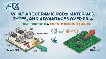
Ceramic PCBs are printed circuit boards that use an inorganic ceramic material as the substrate, replacing the organic epoxy-glass laminate (FR-4) used in conventional boards. This substitution delivers thermal, electrical, and mechanical properties that organic laminates cannot replicate—properties that remain stable across extreme temperature ranges, high frequencies, and harsh chemical environments.
Ceramic Substrate Materials
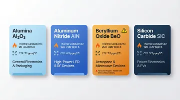
Four primary substrate materials dominate ceramic PCB manufacturing, each with distinct thermal and cost profiles:
| Material | Thermal Conductivity | CTE (ppm/°C) | Best For |
|---|---|---|---|
| Alumina (Al₂O₃) | 24–30 W/m·K | 6–8 | General commercial applications |
| Aluminum Nitride (AlN) | 170–230 W/m·K | 4.5–5.6 | High-power semiconductors, LED arrays |
| Beryllium Oxide (BeO) | 250–300 W/m·K | 6–7 | Specialist use only (carcinogen hazard) |
| Silicon Carbide (SiC) | 120–270 W/m·K | 3.7–4.5 | Extreme temperatures exceeding 800°C |
A few key points worth noting:
- AlN's CTE (4.5–5.6 ppm/°C) closely matches silicon (2.5–3.6 ppm/°C), virtually eliminating thermomechanical stress on solder joints
- BeO dust is a known carcinogen — its use is limited to applications where no alternative material exists
- SiC maintains mechanical integrity at temperatures where both alumina and AlN begin to degrade
Material selection comes down to thermal budget and cost tolerance. Alumina covers most commercial use cases. AlN is the go-to for high-power semiconductors and LED arrays, where junction temperature directly affects both performance and lifespan.
Manufacturing Technology Basis
Ceramic PCBs are produced through specialized processes including:
- Direct Copper Bonding (DCB) — Copper foil is bonded to ceramic at 1,065–1,085°C using a eutectic reaction
- Direct Plated Copper (DPC) — Copper is electroplated directly onto a metallized ceramic surface after thin-film deposition
- Laser Activation Metallization (LAM) — Laser processing activates the ceramic surface for selective metallization
These processes bond or deposit copper conductors directly onto the ceramic surface, which differs from the chemical etching approach used for FR-4. SFX PCB uses DPC technology for all ceramic orders, providing tighter thermal performance and avoiding the microbubble defects that can occur with DCB bonding.
Ceramic manufacturing also enables passive components—resistors and capacitors—to be integrated directly into internal layers during sintering. This contrasts with FR-4, where all passives must be surface-mounted, and opens the door to higher integration density with fewer discrete parts.
Types of Ceramic PCBs
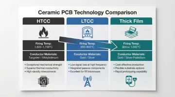
The three main ceramic PCB types are classified by their manufacturing firing temperature and conductor materials. Each type has distinct capabilities, conductor compatibility, and target applications.
High-Temperature Co-Fired Ceramic (HTCC)
HTCC uses raw alumina ceramic mixed with solvents, binders, and plasticizers. Circuit traces are printed using refractory metals—tungsten or molybdenum—before lamination. The entire stack is co-fired at 1,600–1,700°C in a hydrogen atmosphere for up to 48 hours.
HTCC's extreme firing temperature rules out gold or silver conductors — both would melt before the process completes. Tungsten and molybdenum traces carry higher electrical resistance than noble metals, which limits HTCC to applications where that trade-off is acceptable: extreme-temperature aerospace, military hardware, and defense systems.
Key characteristics of HTCC:
- Firing temperature: 1,600–1,700°C in a hydrogen atmosphere
- Conductor materials: tungsten or molybdenum (refractory metals only)
- Best suited for: aerospace, military, and high-temperature defense applications
- Not compatible with gold or silver conductor pastes
Low-Temperature Co-Fired Ceramic (LTCC)
LTCC combines crystalline glass with an adhesive substrate and fires at approximately 850–900°C. This lower temperature enables compatibility with gold and silver conductor pastes, which offer lower resistivity than refractory metals. The reduced firing temperature also produces less warpage and better shrink tolerance.
Key advantages of LTCC:
- Better mechanical strength and thermal conductivity for its firing class
- Superior performance in RF/microwave applications due to stable low dielectric loss
- Ideal for LED lighting and telecommunications where gold/silver conductors deliver lower resistivity
- Enables passive component integration within layers
Thick Film Ceramic
Unlike HTCC and LTCC, thick film ceramic uses a pre-fired substrate. Conductor layers of gold or silver-palladium paste are screen-printed directly onto this fired base and sintered at temperatures below 1,000°C. Conductor layer thickness typically ranges from 10–13 microns.
The key capability: thick film processes allow manufacturers to place interchangeable conductors, resistors, and capacitors on the board. After printing and high-temperature sintering, all passive components can be laser-trimmed to precise values—a capability not available with FR-4 or other ceramic types.
Key Advantages of Ceramic PCBs Over FR-4
| Property | Alumina (Al₂O₃) | Aluminum Nitride (AlN) | FR-4 |
|---|---|---|---|
| Thermal Conductivity (W/m·K) | 24–30 | 170–230 | 0.2–0.5 |
| Max Operating Temp (°C) | 800–1,575 | 800–1,370 | 130–170 (Tg) |
| CTE (ppm/°C) | 6.4–8.2 | 4.5–5.6 | 13–17 (X/Y) |
| Dielectric Constant (1 MHz) | 8.5–9.8 | 8.6–9.0 | 4.2–4.6 |
| Moisture Absorption (%) | 0 | 0 | 0.1–0.15 |
Thermal Conductivity
Thermal conductivity is the most significant performance differentiator. Ceramic substrates have dramatically higher thermal conductivity than FR-4, meaning heat generated by components is dissipated across the entire board surface rather than concentrating at hotspots.
Specific values:
- Aluminum Nitride (AlN): 170–230 W/m·K
- Alumina (Al₂O₃): 24–30 W/m·K
- FR-4: 0.2–0.5 W/m·K
In practice, this means a high-power LED mounted on AlN can operate 40–60°C cooler at the junction compared to the same LED on FR-4, directly extending lifespan and maintaining light output. STMicroelectronics documented a 58% reduction in junction-to-heatsink thermal resistance when switching from standard discrete cooling to AlN Direct Bonded Copper substrates in their power modules.
High-Temperature Resistance
Ceramic PCBs maintain reliable operation at temperatures far beyond FR-4's glass transition temperature (Tg). While FR-4 begins to lose rigidity and risks delamination above 130–170°C, alumina ceramic maintains structural integrity up to 800°C in continuous operation, with maximum service temperatures reaching 1,575°C under no-load conditions.
Aluminum Nitride operates reliably to 800°C in air before surface oxidation becomes significant, with stability to 1,370°C in controlled atmospheres.
Relevant applications include:
- Automotive engine compartments where ambient temperatures routinely exceed 150°C
- Industrial furnace controls and sensors
- Aerospace re-entry environments with extreme thermal cycling
Low Coefficient of Thermal Expansion (CTE)
CTE mismatch is the root cause of solder joint fatigue in thermally cycled electronics. Ceramic PCBs have a CTE that closely matches silicon semiconductor dies, whereas FR-4 expands at a vastly different rate.
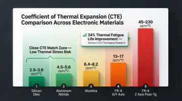
Comparative CTE values (ppm/°C):
- Silicon dies: 2.5–3.6
- Aluminum Nitride: 4.5–5.6
- Alumina: 6.4–8.2
- FR-4 (X/Y axis): 13–17
- FR-4 (Z axis, post-Tg): 45–230
Research on Leadless Ceramic Chip Carriers (LCCCs) subjected to thermal cycling (-55°C to 100°C) demonstrated that replacing FR-4 with alumina substrates increased thermal fatigue life from 635 cycles to 852 cycles—a 34% improvement simply by eliminating CTE mismatch.
This CTE compatibility reduces mechanical stress on solder joints and bond wires during thermal cycling, critical for long-term reliability in automotive and aerospace applications with frequent temperature swings.
Superior Electrical Insulation and Low Dielectric Loss
Beyond mechanical and thermal performance, ceramics offer a distinct electrical advantage: stable dielectric properties that hold up at high frequencies where FR-4 breaks down.
Dielectric properties at 10 GHz:
- Alumina/AlN: Dielectric constant ~8.5–9.8, loss tangent <0.002
- FR-4: Dielectric constant ~3.9–4.2, loss tangent 0.016–0.025
FR-4's higher loss tangent causes measurable signal attenuation above 3–5 GHz. For applications exceeding 10 GHz — 5G mmWave modules, radar, and satellite communications — that degradation becomes a hard engineering constraint, not a tradeoff. Ceramic substrates also support high-voltage isolation due to their dielectric strength, which FR-4 cannot reliably match under thermal stress.
Chemical Resistance, Moisture Resistance, and Mechanical Durability
Ceramic is chemically inert: it resists corrosive chemicals, solvents, and atmospheric moisture that degrade FR-4's epoxy matrix over time. Ceramics absorb zero moisture (compared to FR-4's 0.1–0.15%), eliminating dimensional changes and dielectric shifts in humid environments.
Ceramic's rigidity makes it resistant to warping under physical strain. FR-4 can delaminate under high-vibration conditions common in military and aerospace applications, while ceramic maintains structural integrity. For outdoor deployments, medical devices, and industrial equipment running in harsh conditions, that structural consistency translates directly to longer service life.
Common Applications of Ceramic PCBs
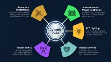
Aerospace, military, and defense: These environments push substrates to their absolute limits — temperature swings from -55°C to +125°C, hard vacuum, constant vibration, and radiation exposure that would degrade FR-4 within months. Ceramic handles all of it. Common applications include:
- Satellite communication modules
- Radar transmit/receive modules
- Missile guidance systems
- Avionics boards
Automotive and power electronics: High current loads and aggressive thermal cycling are the norm here. Ceramic's heat dissipation and CTE-matched substrates prevent solder joint fatigue across 10–15 year service lives — something aluminum-backed FR-4 alternatives struggle to match. Typical applications:
- EV battery management systems
- Motor control units and engine control units (ECUs)
- High-power inverters for solar and renewable energy
LED lighting, medical, and telecom: Around 70% of LED input power converts to heat — ceramic substrates pull that heat away fast enough to protect both the junction and the surrounding components. In medical and RF applications, the drivers are stability and biocompatibility rather than raw thermal load. Applications span:
- High-power LED arrays for automotive and industrial lighting
- Medical sensors, implantable devices, and MEMS
- 5G and RF communication modules requiring stable signal integrity above 10 GHz
When Should You Choose a Ceramic PCB Over FR-4?
Ceramic PCBs are the right choice when:
- Operating temperatures regularly exceed 150°C
- CTE mismatch with silicon dies is causing solder joint fatigue in thermal cycling
- High-frequency signal integrity above several GHz is required
- Exposure to chemicals, moisture, or mechanical vibration makes FR-4 reliability unacceptable
- Zero moisture absorption is critical for dimensional stability
For general-purpose consumer electronics at moderate temperatures, FR-4 remains the cost-effective choice. When ceramic is warranted, however, the cost and design trade-offs deserve a clear look before committing.
Cost and Design Trade-Offs
Ceramic PCBs cost significantly more than FR-4 due to material and manufacturing process complexity. While specific multipliers vary by specification, ceramic substrates are generally 3–10× more expensive than equivalent FR-4 boards, with AlN commanding premium pricing over alumina.
Ceramics are also more brittle than FR-4, requiring careful Design for Manufacturability (DFM) review to avoid substrate cracking during assembly. Key handling and assembly precautions include:
- Edge chamfering to reduce stress concentration points
- Controlled heating and cooling rates during soldering
- Mechanical support fixtures during component placement
- Inspection checkpoints after each thermal cycling stage
Getting DFM analysis done before fabrication — not after — is where most ceramic PCB projects avoid costly mistakes. SFX PCB includes free DFM review on every order, with ISO9001, ISO13485, and IPC-A-610 Class 2/3 certified processes designed for exactly these high-reliability applications.
Frequently Asked Questions
What is a ceramic printed circuit board?
A ceramic PCB is a circuit board that uses ceramic materials—alumina (Al₂O₃), aluminum nitride (AlN), beryllium oxide (BeO), or silicon carbide (SiC)—as the substrate instead of organic FR-4 laminate. Their primary purpose is exceptional thermal performance and reliability in demanding environments.
What is the difference between ceramic printed circuit boards and FR-4?
FR-4 uses glass-reinforced epoxy—low cost and adequate for general use. Ceramic PCBs use inorganic substrates that offer far superior thermal conductivity (up to 575× higher), higher operating temperature limits (800°C vs. 170°C), lower CTE matching silicon, and better chemical resistance, all at significantly higher cost.
How thick is a ceramic printed circuit board?
Ceramic PCB substrate thickness typically ranges from 0.25 mm to 3.0 mm depending on the type (HTCC, LTCC, or thick film) and application. Thinner substrates are used in compact, high-density designs, while thicker substrates provide more mechanical strength and thermal mass.
Which ceramic material—alumina or aluminum nitride—should I choose?
Alumina (Al₂O₃) is the cost-effective choice for most applications with moderate thermal requirements (thermal conductivity 24–30 W/m·K). Aluminum nitride (AlN) is the premium choice when maximum thermal conductivity (170–230 W/m·K) is required—such as high-power semiconductors and LEDs—and budget allows for higher material cost.
Are ceramic PCBs more expensive than FR-4?
Yes, ceramic PCBs are significantly more expensive than FR-4 due to the cost of raw ceramic materials and specialized fabrication processes (HTCC, LTCC, DCB, DPC). That cost premium is justified in mission-critical applications—such as aerospace, medical, or high-power electronics—where long-term reliability outweighs upfront expenditure.
Can ceramic PCBs be manufactured in multilayer configurations?
Yes, ceramic PCBs can be manufactured in multilayer configurations—particularly HTCC and LTCC types—where layers are stacked and co-fired together. This enables high-density interconnects and passive component integration within internal layers, though design complexity and cost increase with layer count.