Introduction
Every electronic device — from a smartphone to a medical monitor — runs on a circuit board packed with dozens of individual components, each performing a specific job the whole system depends on. One misoriented capacitor or an under-rated transistor can cause the entire circuit to malfunction, turning months of design work into a costly rework cycle.
Choosing, identifying, and sourcing the wrong components leads to assembly failures, delayed launches, and field failures that damage brand reputation. Supply chain exposure compounds the risk — during the 2020–2022 semiconductor shortage, 91% of electronics manufacturers delayed product launches due to sourcing issues, with over half of those launches canceled entirely. Engineers and product teams who can't read a BOM or identify a component by its markings have no way to spot these risks before they become expensive.
This guide delivers a complete PCB parts list organized by category, a practical identification method using reference designators and silkscreen markings, and a clear framework for selecting components that are electrically sound, assembly-ready, and supply-chain safe.
Key Takeaways
- PCB components are physical devices mounted on a printed circuit board to perform specific electrical functions: resistors, capacitors, ICs, and connectors are the most common types
- Components fall into six practical categories: Passives, Semiconductors, RF & Antenna, Interconnect & Electromechanical, Protection, and Sensors & Transducers
- Reference designators (R, C, U, D, J, F) printed on the silkscreen are the fastest way to identify an unknown component on a live board
- Right component selection means matching electrical ratings, confirming package compatibility, verifying multi-source availability, and checking RoHS/REACH compliance upfront
What Are Circuit Board Components?
PCB components are the discrete physical devices soldered onto a printed circuit board to realize the board's intended circuit function. The board itself — its substrate, copper traces, vias, solder mask, and silkscreen — is the platform that hosts these components, not a component in its own right.
Mounting Technologies: SMT vs. THT
Two mounting technologies dictate how components attach to a PCB:
| SMT (Surface-Mount) | THT (Through-Hole) | |
|---|---|---|
| How it works | Components sit on copper pads; reflowed in ovens | Leads pass through drilled holes; wave- or hand-soldered |
| Market share | Over 72.7% of modern assembly | Minority share, but irreplaceable in key sectors |
| Key strengths | Miniaturization, high-density layouts, automated placement | Superior mechanical strength, vibration resistance |
| Best for | Consumer electronics, compact designs | High-power applications, connectors, industrial/automotive/medical/aerospace |
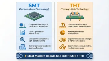
Most production boards combine both technologies — SMT for density and speed, THT where mechanical durability demands it. SFX PCB's assembly operation handles full mixed-technology workflows, pairing reflow soldering for SMT components with wave and selective soldering for through-hole parts.
Why Component Literacy Matters
A single missing or incorrectly specified component can cause the entire circuit to malfunction. Understanding what each component does is essential at every stage — from design through assembly. Misoriented polarized components are a leading cause of board-level failures — and are easily prevented with proper identification.
Complete PCB Parts List: Core Component Categories
Professional BOMs organize components into six categories: Passives, Semiconductors, RF & Antenna, Interconnect & Electromechanical, Protection, and Sensors & Transducers. Grouping components this way makes BOMs easier to audit, source, and assemble.
Passive Components
Passive components — resistors (R), capacitors (C), inductors (L), ferrite beads (FB), crystals/resonators (Y/X), and transformers (T) — store, shape, or dissipate energy without amplifying signals. They require no external power to function and form the backbone of every analog and power circuit.
What separates them is the type of energy they interact with: electrical, magnetic, or frequency-selective.
- Resistors limit current and divide voltages
- Capacitors store charge for decoupling, filtering, and timing
- Inductors store magnetic energy to filter noise and shape current waveforms
- Crystals provide stable clock references for microcontrollers
Common applications include power supply filtering, signal conditioning, EMI suppression, impedance matching, and timing circuits.
Passives make up the largest share — by component count — of almost any PCB BOM. In fact, passive components account for 87% of physical unit volume but only 10% of BOM cost, creating a paradox: cheap parts that can halt multi-million dollar production lines if unavailable.
Critical Design Consideration — MLCC DC-Bias Derating: Class 2 MLCCs (X5R, X7R dielectrics) experience a severe drop in effective capacitance when DC voltage is applied. Depending on the part and applied voltage, an MLCC can lose 40–50% or more of its rated capacitance. Failing to account for this derating can lead to unstable power delivery, abnormal oscillation in DC-DC converters, and erratic circuit behavior.
Semiconductor Components
Semiconductors — diodes (D), LEDs, TVS diodes, transistors/MOSFETs/IGBTs (Q), and integrated circuits (U/IC) — actively control or amplify electrical signals when powered. ICs package entire functions such as microcontrollers, memory, voltage regulators, and communication interfaces into a single body.
- Diodes allow current in one direction (or emit light, or clamp surges)
- Transistors and MOSFETs switch or amplify signals
- ICs integrate dozens to billions of transistors for complex digital, analog, or mixed-signal functions
The scale of integration spans a wide spectrum — from a single-function discrete device to a fully packaged system-on-chip. Apple's M1 Ultra contains 114 billion transistors; Nvidia's H100 GPU scales to 80 billion.
Typical use cases include signal amplification, digital logic, power switching, voltage regulation, memory storage, and wireless communication.
ICs are typically the highest-value components on a board and the most critical to source carefully. Active components consume 90% of the typical BOM budget while accounting for only 13% of component count.
Interconnect, Protection, and Sensing Components
Beyond active and passive components, three additional categories define how a board interfaces with the world — and how it survives it.
Interconnect & Electromechanical (J/P, SW, K, M): These components define how a PCB communicates with the outside world and are often the largest mechanical elements on the board:
- Connectors provide removable electrical interfaces between boards and external systems
- Switches give users direct manual control
- Relays allow electrically isolated switching for higher-power or separate circuits
- Motors and buzzers convert electrical signals to physical action or sound
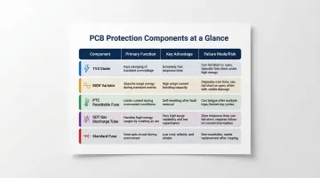
Protection Components (F, MOV, TVS, GDT): Fuses and resettable PTCs interrupt or limit overcurrent; metal-oxide varistors (MOVs) and TVS diodes clamp voltage transients and ESD events; gas discharge tubes divert high-energy surges.
| Component Type | Primary Function | Key Advantage | Failure Mode / Risk |
|---|---|---|---|
| TVS Diode | Voltage clamping (ESD/EFT) | Nanosecond response, precise clamping, no wear-out | Fails short (safe for circuit, but requires a series fuse) |
| MOV (Varistor) | High-energy surge absorption | Can absorb thousands of joules | Degrades with each surge; risk of thermal runaway if not fused |
| PTC (Resettable) | Overcurrent protection | Automatically resets after fault clears | Slower reaction time than TVS; degrades over many thermal cycles |
| GDT | Extreme surge diversion | Highest surge current rating | Slow response time; allows high let-through voltage |
| Standard Fuse | Permanent overcurrent halt | Failsafe circuit break (governed by UL 248) | Requires physical replacement after tripping |
Skipping protection components to shave BOM cost is a false economy — field failures, regulatory rejections, and liability exposure in consumer, industrial, and medical products routinely cost far more than the components that would have prevented them.
Sensors & Transducers: Temperature sensors (thermistors, ICs), pressure sensors, IMUs, Hall-effect sensors, and optical/gas sensors convert physical or environmental conditions into measurable electrical signals. These components are especially critical in IoT, medical, and automotive applications where real-world data drives device decisions.
How to Identify Circuit Board Components
Reference Designators (RefDes)
Every component on a labeled PCB is assigned a reference designator printed in silkscreen — a letter prefix identifying the component type followed by a unique number (e.g., R45 = resistor 45, C12 = capacitor 12, U3 = integrated circuit 3, J1 = connector 1).
Common Reference Designators:
| Prefix | Component Type | Standard Source |
|---|---|---|
| R | Resistor | IEEE 315 |
| C | Capacitor | IEEE 315 |
| L | Inductor / Coil | IEEE 315 |
| U | Integrated Circuit | IEEE 315 |
| D / CR | Diode (including LEDs) | IEEE 315 |
| Q | Transistor | IEEE 315 |
| J | Jack / Connector | IEEE 315 |
| F | Fuse | IEEE 315 |
| S / SW | Switch | IEEE 315 |
| Y | Crystal / Oscillator | IEEE 315 |
| T | Transformer | IEEE 315 |
| TP | Test Point | IEEE 315 |
| FB | Ferrite Bead | Industry standard |
Polarity and Orientation Markers
Polarity-sensitive components carry physical orientation markers that must be read correctly before placement or troubleshooting:
- Diodes have a cathode stripe
- Electrolytic capacitors have a "–" bar or a shorter lead
- ICs have a Pin-1 dot or notch on the body
- QFN and BGA packages have a Pin-1 corner marker
Misoriented polarized components are a leading cause of board-level failures and are easily prevented with proper identification.
Reading Top-Mark Codes and Package Types
Alphanumeric codes printed on component bodies (top marks) can be cross-referenced against a datasheet or BOM. Package type provides clues about power level, pin count, and mounting method. Common package formats include:
- SOT-23, SOT-323 — small-signal discretes, low pin count
- SOIC, SSOP — ICs with gull-wing leads, easy to inspect visually
- QFP — higher pin-count ICs with perimeter leads
- QFN, DFN — leadless packages, compact footprint
- BGA — high-density ICs with hidden solder balls underneath
- TO-220, TO-247 — through-hole power components
BGAs and other hidden-lead packages require X-ray inspection to verify solder joint integrity. Confirm that your assembler has in-house X-ray capability before finalizing BGA package selection — it's the only reliable method for detecting voids, solder bridges, and head-in-pillow defects.
Using the BOM and Centroid File for Identification
A complete Bill of Materials (BOM) links each RefDes to its value, manufacturer part number (MPN), package footprint, and description. The Centroid (Pick-and-Place) file adds the X/Y coordinates, board side (top/bottom), and rotation angle that automated assembly machines rely on.
Cross-check silkscreen markings, BOM values, and the Centroid file together when auditing an unknown board or troubleshooting a suspected placement error.
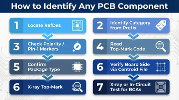
Practical Identification Checklist
- Locate the RefDes on the silkscreen
- Identify the component category from the letter prefix
- Check polarity/Pin-1 markers
- Read the top-mark code and match to BOM or datasheet
- Confirm package type and footprint
- Verify board side and rotation using the Centroid file
- For BGAs or unlabeled components, use X-ray inspection or in-circuit testing to validate electrically
How to Choose the Right PCB Components
Match Electrical Ratings with Adequate Margin
Every component must be selected with rated values that exceed worst-case operating conditions:
- Capacitors need voltage headroom above the DC bias (accounting for DC bias derating in ceramic caps)
- Inductors must not saturate at peak current
- MOSFETs must have RDS(on) evaluated at the actual gate drive voltage
- Resistors need power ratings well above calculated dissipation
Under-rating components is a leading driver of field failures — and one of the easiest to prevent at the design stage.
Verify Package Compatibility with Your Assembler Early
Choosing a component package that your assembly partner cannot reliably place, inspect, or rework creates expensive bottlenecks. Confirm:
- Minimum pitch capability (e.g., 0.4 mm QFN/BGA)
- Smallest placeable component size (e.g., 0201/01005)
- Stencil thickness compatibility
- Whether X-ray inspection is available for hidden-lead packages
SFX PCB's assembly line handles components down to 01005 (0402 metric), BGAs with 0.25mm pitch, and placement precision of ±0.035mm. Every order includes a free DFM (Design for Manufacturability) analysis that catches package and footprint mismatches before production — before they become rework costs.
Package compatibility and sourcing availability are two sides of the same coin: a component that can be placed but not reliably procured creates just as much risk.
Prioritize Multi-Source Availability and Supply Chain Resilience
Select components with at least one approved alternate in the same footprint from a different manufacturer. During the 2020–2022 shortage, 91% of electronics manufacturers delayed product launches due to sourcing issues, with lead times for critical components like microcontrollers stretching from 30 to 50+ weeks.
Maintain an approved vendor list and monitor inventory and end-of-life (EOL) status through distribution channels. SFX PCB's sourcing team carries access to over 600,000 parts in local stock and can identify qualified alternates when primary parts are constrained or approaching EOL.
Confirm RoHS, REACH, and Application-Specific Compliance
Components must comply with the regulatory standards of every target market:
- RoHS restricts hazardous substances in EU and many other markets
- REACH addresses chemical safety
- Sectors like automotive (AEC-Q standards), medical (IPC-A-610 Class 3), and aerospace carry additional qualification requirements
| Regulation | Jurisdiction | Key Focus | Effective Date |
|---|---|---|---|
| EU RoHS 3 | European Union | Restricts 10 substances (Lead, Mercury, Cadmium, Hexavalent chromium, PBB, PBDE, 4 Phthalates) | Current |
| China RoHS | China | Transitioning to mandatory national standard aligning with EU RoHS | GB 26572-2025 (August 2027) |
| REACH | European Union | Registration and restriction of SVHCs | Regulation (EC) No 1907/2006 |
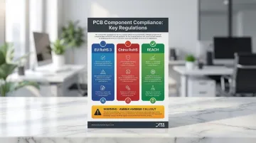
Non-compliant components can block market entry or trigger costly redesigns late in the product lifecycle. China's shift to GB 26572-2025 means companies must prepare for strict, mandatory enforcement of the 10 restricted substances by 2027.
Total Cost of Ownership Matters More Than Unit Price
Unit price is only one factor — real cost includes:
- Assembly time
- Yield impact
- Test complexity
- The need for heatsinks or EMI fixes
- Rework rate
A slightly more expensive IC that integrates several discrete functions often cuts total BOM cost, reduces board area, and simplifies assembly. Run the full cost model before locking in a component — unit price rarely tells the whole story.
Common PCB Component Selection Mistakes to Avoid
Over-Specifying Where It Doesn't Help
Selecting military-grade or ultra-low-tolerance components for a consumer application where standard grades would suffice drives up cost and can create procurement bottlenecks without improving real-world performance. The right specification matches the application's actual demands, not the engineer's maximum comfort.
Ignoring Package and Footprint Constraints Until It's Too Late
Component package selection is often made at the schematic stage without consulting the assembler's capabilities: this leads to mismatched land patterns, tombstoning on small passives, or BGA packages the assembly line cannot inspect.
As passives shrink to 0201 and 01005 sizes, they become highly susceptible to "tombstoning" (the Manhattan effect). Unequal surface tension forces from molten solder cause one end of the component to lift vertically, breaking the electrical connection.
Prevention strategies include:
- Implementing "reverse U-shape" stencil apertures to reduce solder paste volume on pad edges
- Using soak-type reflow profiles to allow thermal equilibrium before entering the liquidus phase
- Switching to anti-tombstoning solder pastes
Run DFA (Design for Assembly) review alongside component selection — not after layout is complete.
Choosing Single-Source Components Without an Approved Alternate
Relying on a single-source component (especially a proprietary or end-of-life part) creates severe supply chain vulnerability. If that part goes into shortage or reaches EOL, the entire production run is at risk.
To protect your program:
- Identify a form-fit-function alternative in the same footprint before design is finalized
- Document approved alternates in the BOM from day one
- Flag single-source parts during DFM review so procurement can act early
Conclusion
Understanding component categories, identification conventions, and selection criteria is what separates designs that manufacture reliably at scale from those that generate costly surprises on the production floor. That gap shows up in rework costs, delayed launches, and field failures — all of which trace back to decisions made early in the design cycle.
The right component choices — made early, validated through DFM/DFA analysis, and backed by a reliable sourcing strategy — shape product quality, launch timelines, and total manufacturing cost more than most teams anticipate.
For teams looking to manage that complexity without switching suppliers at each stage, SFX PCB provides turnkey PCBA services covering component sourcing, assembly, and testing — certified to IPC-A-610 Class 2/3 standards for both prototype and production volumes.
Frequently Asked Questions
What is PCB and its components?
A PCB (Printed Circuit Board) is a flat board of non-conductive substrate with copper traces that connect electronic components. Its components — resistors, capacitors, ICs, connectors, and more — are physical devices soldered onto the board to perform specific electrical functions.
What are the parts of a circuit board?
A circuit board has two categories of parts: the board structure (substrate, copper traces, vias, solder mask, silkscreen) and the placed components (passives, semiconductors, connectors, protection devices, sensors). The components are soldered onto the structure to form a working circuit.
What parts of a circuit board are valuable?
Integrated circuits (CPUs, FPGAs, memory chips), high-frequency RF components, and precision sensors are the most valuable by cost and function. Gold-plated contacts carry material value, while passives like resistors and capacitors are cheap but equally critical to circuit operation.
What is the difference between active and passive components on a PCB?
Passive components (resistors, capacitors, inductors) store or dissipate energy without amplifying signals — no external power needed. Active components (transistors, ICs, diodes) control, switch, or amplify signals, but only when an external power supply is connected.
What do the letters and numbers on a circuit board mean?
The letters and numbers are reference designators (RefDes) printed in silkscreen. The letter identifies the component type (R = resistor, C = capacitor, U = IC, J = connector), and the number is a unique identifier linking it to the schematic and Bill of Materials.
How do you read a PCB component list (BOM)?
A BOM (Bill of Materials) lists each component by reference designator, quantity, value or rating, manufacturer, part number (MPN), and package footprint. Cross-referencing it with the silkscreen RefDes and Centroid file lets assemblers and QC teams confirm the right part is placed in the right location with the right orientation.