Introduction
PCB failures rarely announce themselves. They creep in through degraded capacitors, shorted diodes, or hairline trace fractures that only surface under load. For engineers and technicians troubleshooting prototype boards or diagnosing field returns, the digital multimeter (DMM) is the first-line diagnostic tool for isolating faults before they compound into costly, hard-to-trace failures.
Knowing how to test individual components is essential for catching defects before they escape. The cost difference is stark: a fault caught at the bench costs roughly $1 to fix. That same defect in production runs $10. Reach the customer, and you're looking at $100 or more in warranty claims and reputational damage.
This guide covers everything you need to test PCB components accurately:
- Step-by-step procedures for resistors, capacitors, diodes, transistors, and traces
- How to configure your multimeter correctly for each test
- What readings indicate healthy versus faulty components
- The most common mistakes that produce misleading results
Key Takeaways
- Power down and discharge capacitors before testing resistance, continuity, or capacitance; only probe live circuits when measuring voltage
- Use the correct mode: resistance (Ω) for resistors, capacitance (F) for capacitors, diode mode for diodes and transistors
- Continuity mode checks PCB traces for shorts (beep = connected) or opens (silence = broken path)
- Good readings match rated values; unexpected 0Ω means a short, OL where continuity is expected means a break
- In-circuit readings can be skewed by parallel paths; desolder one lead to test a component in isolation
What You Need to Test PCB Components with a Multimeter
Accurate PCB component testing depends on selecting the right multimeter mode and ensuring the board is in the correct state. Wrong settings or probing a powered board can damage components, blow the meter's internal fuse, or produce misleading readings that send you chasing phantom faults.
Tools Required
Essential Equipment:
- Digital multimeter (DMM) with resistance (Ω), continuity, diode, and capacitance modes
- Insulated test probes in good condition with intact rubber boots and sharp, clean tips
- PCB schematic or component datasheets for reference values and pinouts
- Desoldering tools (solder sucker, desoldering braid, or hot air station) if removing components for isolated testing
- ESD-safe wrist strap and anti-static mat to prevent electrostatic discharge damage
Digital vs. Analog Multimeters:
Digital multimeters are strongly preferred for PCB component testing. Three practical advantages make them the better choice:
- Auto-ranging adjusts the measurement range automatically, protecting against overload damage from incorrect range selection
- Dedicated diode test mode applies the precise forward bias voltage needed for semiconductor junction testing — something analog meters can't do
- Digital displays eliminate needle-reading ambiguity and deliver precise readings essential for verifying component tolerances
Preconditions and Setup
Power Down the Board:
Before testing resistance, continuity, or capacitance, power off the circuit completely. Attempting these measurements on energized boards will damage the multimeter's internal fuse and can destroy the component under test. Only measure voltage on powered circuits. Verify the board is de-energized by checking with the DMM's voltage mode first.
Discharge Capacitors Safely:
Capacitors store energy even after power is removed. Before probing, discharge them using a high-wattage resistor (20,000Ω, 5-watt rating) connected across the terminals for five seconds. Never short capacitor terminals directly with a screwdriver—this can damage the component and create a safety hazard.
Probe Setup:
Insert the red probe into the VΩmA port and the black probe into the COM (common) port. Verify probe continuity by touching the probe tips together—the meter should beep (in continuity mode) or read near 0Ω (in resistance mode). Select the appropriate measurement mode or enable auto-range if available.
How to Test PCB Components with a Multimeter
This section covers hands-on testing procedures for the five most common PCB components and board-level connections:
- Resistors
- Capacitors
- Diodes
- Transistors
- PCB traces and continuity
For a quick diagnostic check, in-circuit testing is acceptable. For definitive fault isolation, desolder at least one lead to eliminate parallel path interference before retesting.
Testing Resistors
Procedure:
- Set the multimeter to resistance (Ω) mode
- Place probe tips across both resistor terminals (polarity doesn't matter)
- Read the displayed value
- Cross-reference against the resistor's color-band code or labeled value
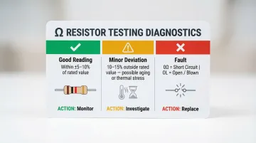
Interpreting Results:
- Reading within ±5–10% of the rated value is normal (most commercial resistors carry ±5% tolerance per IEC 60062)
- Shorted: Reading of 0Ω or near-zero indicates the resistor has failed internally
- Open/Blown: OL (overload) display means the resistor has an open circuit and must be replaced
In-Circuit Considerations:
Parallel resistors or other components in the same net will lower the displayed resistance. If the reading falls significantly below the rated value but the resistor appears visually intact, desolder one lead and retest in isolation.
Testing Capacitors
Safe Discharge First:
Before testing, discharge the capacitor using a 20,000Ω, 5-watt resistor held across the terminals for five seconds. This prevents meter damage from stored charge.
Method 1: Capacitance Mode (Preferred)
- Set the multimeter to capacitance (C/F) mode
- Connect the red probe to the positive terminal and black probe to the negative terminal (observe polarity for electrolytic capacitors)
- Read the displayed capacitance value
- Compare to the rated value on the component body or datasheet
Expected Tolerances:
- Aluminum electrolytic: ±20% typical
- Ceramic (X7R): ±10–20%
- Film capacitors: ±5–20%
Method 2: Resistance Mode (No Capacitance Function)
- Set the multimeter to the highest resistance range
- Touch probes to capacitor terminals
- Watch for a brief low-resistance reading that climbs steadily toward OL—this charging behavior confirms a healthy capacitor
- Consistently low reading (near 0Ω): Capacitor is shorted internally
- Immediate OL with no needle movement or climb: Capacitor is open/failed
Testing Diodes
Procedure:
- Set the multimeter to diode mode (diode symbol)
- Forward bias test: Place the red probe on the anode and black probe on the cathode
- Read the forward voltage drop (Vf)
- Reverse bias test: Reverse the probes—reading should show OL (no conduction)
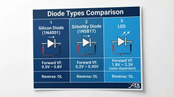
Expected Forward Voltage Drops:
| Diode Type | Forward Voltage (Vf) | Reverse Bias Reading |
|---|---|---|
| Silicon diode (e.g., 1N4001) | 0.5V to 0.8V | OL (overload) |
| Schottky diode (e.g., 1N5817) | 0.2V to 0.45V | OL (overload) |
| LED | 1.8V to 3.3V (color-dependent) | OL (overload) |
Fault Indicators:
- Shorted diode: ~0V reading in both forward and reverse directions
- Open/dead diode: OL in both directions
- Readings outside the expected Vf range but not at 0V or OL point to partial degradation—replace the component rather than relying on it under load
Testing Transistors
Identify Terminals:
Use the component datasheet or physical markings to identify the Base (B), Collector (C), and Emitter (E) terminals. Bipolar junction transistors (BJTs) can be tested by treating them as two back-to-back diodes.
NPN Transistor Test:
- Set the multimeter to diode mode
- Red probe on Base, black probe on Collector → should show ~0.6–0.7V forward drop
- Red probe on Base, black probe on Emitter → should show ~0.6–0.7V forward drop
- Reverse both probe orientations → both should read OL (no conduction)
PNP Transistor Test:
Reverse the probe polarity:
- Black probe on Base, red probe on Collector → ~0.6–0.7V
- Black probe on Base, red probe on Emitter → ~0.6–0.7V
- Reverse both orientations → both should read OL
Fault Indicators:
- 0V in all directions: Transistor is shorted
- OL in all directions: The junction has blown open — replace the transistor
- Inconsistent readings suggest partial failure or incorrect terminal identification
Once individual components pass testing, the next step is verifying the board-level connections that link them together.
Testing PCB Traces for Continuity
Procedure:
- Set the multimeter to continuity mode (speaker/diode symbol)
- Touch probes to both ends of a suspect trace or between two pads that should be electrically connected per the schematic
- Continuous beep: Trace is intact and conducting properly
- Silence/no beep: Open break in the trace requiring repair
Checking for Unintended Shorts:
- Place probes on two traces that should NOT be connected according to the schematic
- Beep or near-zero resistance: Indicates a short caused by solder bridges, etching defects, or contamination
- No beep/high resistance: Traces are properly isolated
Continuity Threshold Awareness:
DMM continuity beepers activate at different resistance thresholds depending on the manufacturer and range setting. For example, some meters beep at <10Ω, others at <40Ω. A 30Ω trace might register as "continuous" but actually indicate a degraded, high-resistance connection that could fail under load.
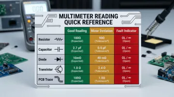
How to Interpret Your Multimeter Readings
Raw numbers on a multimeter screen only become actionable when compared against the component's datasheet specification and the circuit context. Use this reference framework to determine whether a reading indicates a healthy component, minor deviation, or critical fault.
| Component Type | Expected Good Reading | Minor Deviation Threshold | Out-of-Spec / Fault Indicator |
|---|---|---|---|
| Resistor | Within ±5–10% of rated value | ±10–15% (aging/thermal stress) | 0Ω (short) or OL (open) |
| Capacitor | Within ±10–20% of rated capacitance | Slightly below spec (ESR increase) | 0Ω (short), no charge behavior (open) |
| Diode | Vf: 0.5–0.8V (silicon), OL reverse | Vf slightly outside range | 0V both directions (short), OL both ways (open) |
| Transistor | Base junctions: ~0.6–0.7V forward, OL reverse | Slightly lower Vf | 0V all directions (short), OL all directions (open) |
| PCB Trace | Continuity beep, near 0Ω | <10Ω (trace resistance) | OL (open trace), 0Ω between isolated traces (short) |
Normal / Acceptable Readings
Healthy component indicators:
- Resistor: Reading matches color code within tolerance
- Capacitor: Capacitance within ±10–20%, or steady charge behavior in resistance mode
- Diode: Expected Vf in forward bias, OL in reverse
- Transistor: Consistent ~0.6–0.7V drops across Base-Emitter and Base-Collector junctions
- Trace: Continuity beep on connected pads, silence on isolated traces
If readings fall within these ranges, reinstall the component and move on — no further testing needed.
Minor Deviations
Slight out-of-tolerance readings—such as a resistor reading 10–15% outside its rated value or a capacitor slightly below specification—may indicate component aging, thermal stress, or marginal solder joints.
When to monitor vs. replace:
- Monitor: If the circuit still functions correctly and the deviation is <15%
- Replace: If the component is in a critical signal path, high-reliability application, or shows progressive drift over time
Out-of-Spec / Fault Indicators
When a reading crosses into fault territory, the component typically needs replacement — not adjustment or monitoring. Clear fault signs include:
- 0Ω across a component that shouldn't be shorted
- OL where continuity is expected (open circuit)
- Diode or transistor showing 0V in both forward and reverse bias (dead short)
- Capacitor showing no charge behavior or staying at 0Ω (shorted)
Before swapping the component, inspect the surrounding board. Look for burnt traces, discolored solder mask, or signs of overvoltage — a failed diode or shorted capacitor often points to a larger circuit issue. Replacing the part without fixing the underlying cause typically leads to the same fault returning.
Common Mistakes When Testing PCB Components with a Multimeter
In-Circuit Interference
Touching probes to a component with other resistors, diodes, or capacitors in parallel produces skewed readings — the most common source of false "faults." The measured value includes all parallel paths, not just the target component. To avoid this, desolder at least one lead and test the component in isolation.
Probe Placement Errors
- Resting probes on solder mask instead of bare metal pads
- Applying insufficient pressure to ensure good electrical contact
- Accidentally bridging to an adjacent pad or trace
All of these produce unreliable or misleading readings. Always probe on exposed copper, apply firm pressure, and visually confirm probe placement.
Testing Charged Capacitors
Probing capacitors without discharging them first can blow the multimeter's internal fuse or damage its circuitry. Always discharge capacitors using a high-wattage resistor before testing.
Probing Powered Boards in Resistance/Continuity Mode
Measuring resistance, continuity, or capacitance on a live circuit can destroy the multimeter's fuse, damage the meter, or harm the component under test. Always power off and discharge energy storage components before any non-voltage measurements.
Safety and Best Practices
Critical Safety Precautions:
- Power off completely before testing resistance, continuity, or capacitance
- Discharge all capacitors using a 20,000Ω, 5-watt resistor before probing
- Use ESD protection (wrist strap grounded to the workbench, anti-static mat) when handling bare boards—static discharge above 100V can cause latent component damage
- Verify probe insulation and multimeter fuse integrity before use
- Never exceed the multimeter's rated voltage range — check the CAT rating (CAT III/IV) to confirm it matches the circuit under test
Best Practices for Accurate Testing:
- Work with schematics or datasheets to know the expected reading before you probe
- Label or photograph suspect components before desoldering to ensure correct reinstallation
- Test at room temperature — thermal drift can skew readings on hot or cold components
- Use auto-ranging mode to prevent range selection errors and overload damage
- Retest in isolation if in-circuit readings fall outside expected tolerances
Production-Level Quality Assurance
For high-volume manufacturing, manual multimeter testing is a first-pass diagnostic tool — not a complete quality system. Production partners like SFX PCB layer in additional methods to catch what manual probes miss on densely packed SMD assemblies:
- Automated optical inspection (AOI) — flags solder defects and component misalignment
- X-ray inspection — reveals hidden BGA solder joint failures
- Functional circuit testing (FCT) — verifies 100% operational performance under real conditions

SFX PCB performs 100% electrical testing on every bare board before assembly, checking for trace continuity, shorts, and impedance compliance. Combined with ISO9001, ISO14001, and ISO13485 certified processes, every board meets IPC-A-610 Class 2/3 standards before a single component is soldered.
Frequently Asked Questions
Can you test circuit board components without desoldering them?
In-circuit testing is possible and often the first diagnostic step, but parallel components in the same electrical network can skew readings. For a definitive result on suspect components, desolder at least one lead and test in isolation to eliminate parallel path interference.
What multimeter mode should I use to check for a short circuit on a PCB?
Use continuity mode to check for shorts between traces or pads that should not be connected. A beep or near-zero resistance reading confirms an unintended short. Readings below 10Ω in resistance mode typically indicate a direct short requiring immediate investigation.
How do I know if a capacitor is bad using a multimeter?
In capacitance mode, a reading more than 20% below the rated value suggests degradation. In resistance mode, a sustained 0Ω reading indicates a short; immediate OL with no charge behavior points to an open or failed capacitor.
Can using a multimeter damage components on a circuit board?
Yes. Testing in resistance or continuity mode on a powered board can blow the multimeter's fuse and harm components; charged capacitors can damage the meter as well. Always power off the board and discharge capacitors before taking non-voltage measurements.
What does OL mean on a multimeter when testing a PCB component?
OL stands for overload or open-loop, meaning the reading exceeds the meter's selected range. In diode mode, OL is normal in reverse bias. In resistance mode on a trace, OL indicates a break in continuity requiring repair.
When should I use a multimeter versus professional PCB testing equipment?
A multimeter suits prototype debugging, field troubleshooting, and isolating single failed components. Production boards require automated methods — AOI, ICT, X-ray inspection, and functional testing — to verify assembly quality at scale and catch defects that manual probes cannot reach.