Key Takeaways
- LED display circuits use row-column matrix wiring, with microcontrollers driving LEDs through multiplexing
- Wireless scrolling displays need a capable controller (ESP32 is a common pick), a frame buffer, and PWM brightness control
- Resistor sizing and driver IC choice directly determine display quality and thermal stability
- PCB layer count, copper weight, and trace routing must align with your pixel density
- Most failures trace back to wrong resistor values, poorly tuned scan rates, or insufficient heat dissipation
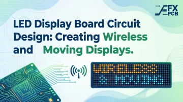
How to Design an LED Display Board Circuit for Wireless and Moving Displays
Step 1: Define Your Display Layout and Matrix Configuration
Start by deciding your pixel resolution—8x8 for simple displays, 16x32 or larger for complex signage. This determines the number of rows, columns, and scan zones your circuit must support.
Choose between common-anode and common-cathode configurations. In a common-cathode matrix, LED cathodes in each row tie together and sink current, while anodes are driven individually to source current. Common-anode reverses this: anodes tie together (sourcing current) while columns sink current.
This electrical difference dictates how your controller sources or sinks current and which driver ICs you can use. The MAX7219, for example, is explicitly designed for common-cathode matrices.
Determine your color requirements:
- Single-color: Simplest routing, minimal driver complexity
- Bi-color: Requires separate control for two LED types per pixel
- RGB: Demands three times the driver capacity and significantly more complex PCB routing
Color depth requirements directly influence driver IC selection and board complexity.
Step 2: Select Components—LEDs, Resistors, Driver ICs, and Controller
Calculate current-limiting resistors using the formula:
R = (Vsupply – Vf) / If
Where Vf is LED forward voltage and If is forward current. For example, driving a red LED (Vf = 1.85V) at 20mA from a 5V supply requires:
R = (5V – 1.85V) / 0.020A = 157.5Ω (use 150Ω standard value)
Critical mistake: Using a single shared resistor per row causes severe brightness variation. When multiple LEDs activate simultaneously, they share current, drastically reducing per-LED brightness. Each additional LED in the row reduces current to all others.
Select appropriate driver ICs:
| Driver IC | Output Current | Best For |
|---|---|---|
| MAX7219 | 40mA per segment, 500mA per digit | Common-cathode matrices up to 64 LEDs; includes multiplex logic |
| 74HC595 | 6mA continuous (35mA absolute max) | Must pair with external transistors for LED driving |
The MAX7219 solves the shared resistor problem with a single external resistor that programs internal constant-current sources, ensuring uniform brightness regardless of how many LEDs are active. The chip sources up to 40mA per segment and includes 16-step PWM brightness control.
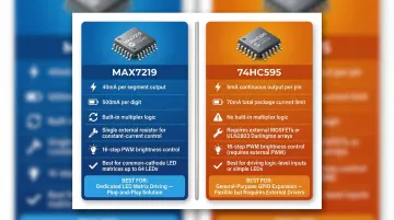
The 74HC595 shift register is more constrained: its entire package is restricted to 70mA through VCC or GND. You cannot safely direct-drive high-brightness LEDs with 74HC595s alone; pair them with external MOSFETs or Darlington arrays like the ULN2803.
Choose your microcontroller:
- Arduino (ATmega328P): Sufficient for simple wired displays; 5V native operation; limited to 14 digital GPIO
- ESP32: Required for wireless displays; integrates Wi-Fi and Bluetooth; 34 GPIO; operates at 3.3V (requires level shifting for 5V drivers)
Check current sourcing limits before direct-driving LEDs. The ATmega328P and ESP32 both have 40mA absolute maximum per pin, but sustained operation should stay at 20mA or below to prevent overheating.
Step 3: Create the Schematic and PCB Layout
Draft your schematic showing the complete row-column matrix, driver IC connections, and microcontroller interface. Include decoupling capacitors (0.1µF ceramic) on power rails near every driver IC. Omitting them is one of the most common causes of display flickering.
PCB layer selection:
- 1-2 layers: Sufficient for simple single-color displays with large pixel pitch (P8-P10)
- 4 layers: Required for high-density or RGB displays; provides dedicated power and ground planes that reduce EMI and improve signal integrity
- 6+ layers: Necessary for very high-density displays or when integrating wireless modules like the ESP32, which requires strict 50Ω impedance control and continuous ground planes
Apply Design for Manufacturability (DFM) principles:
- Maintain trace width appropriate for LED current loads (use IPC-2152 standard as reference)
- Keep traces between driver ICs and LED columns short to minimize resistance drop
- Ensure adequate copper weight: 1 oz (35µm) is standard; high-density RGB displays may require 2 oz (70µm) for better current capacity and thermal management
- Verify copper weight capabilities with your manufacturer
SFX PCB provides free DFM analysis before fabrication, catching routing errors, insufficient copper weight, and thermal issues before boards are built. This prevents costly rework and reduces turnaround time.
Step 4: Program the Controller for Multiplexing and PWM
Implement row-column multiplexing in firmware: the controller activates one row at a time while setting column outputs for that row's LED pattern. Cycle through all rows fast enough (typically 100Hz+ total refresh) that the human eye perceives a continuous image.
For PWM-based brightness control, vary the on-time of each row during the multiplexing cycle. Insufficient refresh rate causes visible flicker, especially under camera exposure. For displays used in broadcast or video environments, target a minimum refresh rate of 3,840Hz to prevent rolling scan lines and banding artifacts.
For scrolling text, implement a frame buffer array in memory storing the full message as a bitmap. Achieve scrolling by shifting the buffer one column at a time at set intervals, then re-rendering the active display window. This separates content management from display refresh, keeping the multiplexing loop running smoothly.
Step 5: Integrate Wireless Control and Test the Full Circuit
For wireless displays, configure the ESP32's Wi-Fi or Bluetooth stack to receive text strings or display commands from a mobile app or host device. Use lightweight protocols:
- Bluetooth (BLE): Best for short-range, low-power applications like retail shelf displays
- Wi-Fi (HTTP/WebSocket): Enables cloud-connected displays receiving updates from central content management systems
Once wireless communication is confirmed, validate the full display circuit systematically:
- Verify LED forward voltage and brightness uniformity across all positions
- Check for ghosting artifacts caused by slow multiplexing or insufficient row discharge
- Confirm wireless command reception and display update latency
- Measure refresh rate with an oscilloscope to ensure it meets your target (1000Hz minimum for indoor signage, 3840Hz+ for video environments)
What You Need Before Starting Your LED Display Board Circuit
Preparation determines whether your build succeeds on the first attempt or requires multiple debug-rework cycles.
Equipment and Component Requirements
Minimum required:
- Regulated DC power supply (3.3V or 5V depending on LED specs)
- Microcontroller development board (Arduino or ESP32)
- LED matrix or individual LEDs
- Driver ICs (MAX7219 or 74HC595 with transistor arrays)
- Current-limiting resistors
- Breadboard or custom PCB
- Soldering tools
- Logic analyzer or oscilloscope for signal debugging
Skill and Software Readiness
Before diving into hardware, confirm you have these skills covered:
- Schematic capture in KiCad or EasyEDA
- Coding in Arduino IDE or ESP-IDF (for ESP32 builds)
- BLE GATT profiles or Wi-Fi socket programming (wireless builds only)
If you're moving to a custom PCB, prepare Gerber files that match your manufacturer's design rules. For production builds, request DFM feedback before ordering to catch layer count, trace width, or pad size issues early. SFX PCB provides free DFM analysis and responds to design submissions within 24 hours, catching problems before fabrication begins.
Key Parameters That Affect LED Display Board Circuit Performance
Even correctly wired circuits will underperform or fail if key design variables aren't tuned to match pixel density, environment, and intended use.
Multiplexing Ratio and Scan Rate
The multiplexing ratio (1/4 scan, 1/8 scan, 1/16 scan) determines how many rows drive simultaneously. Higher ratios reduce power draw and pin count, but they also decrease effective per-LED brightness and increase flicker risk — a direct tradeoff that shapes your driver IC count and LED selection.
- 1/4 scan: Four rows lit simultaneously; high brightness but requires more driver ICs
- 1/8 scan: Two rows lit at a time (in 16-row modules); standard balance of brightness and cost
- 1/16 scan: One row lit at a time; requires fewer ICs but demands much higher refresh rates
For indoor displays, 1/4 to 1/8 scan rates work well. Higher scan counts require brighter LEDs or higher peak current drivers to compensate for reduced duty cycle per LED. This duty-cycle reduction connects directly to the next variable: PWM frequency.
PWM Frequency and Refresh Rate
PWM frequency controls brightness gradation and determines whether displays flicker visibly on camera. Too low a refresh rate produces banding in video footage and visible flicker in low-light environments.
| Application | Minimum Refresh Rate | Rationale |
|---|---|---|
| Standard Indoor Signage | > 1,000 Hz | Eliminates phantom array effects during eye saccades |
| Broadcast / Live Streaming | ≥ 3,840 Hz | Prevents rolling scan lines on 30/60fps cameras |
| XR / Virtual Production | ≥ 7,680 Hz | Required for high-speed filming and genlocked cameras |
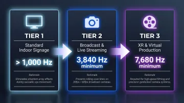
These thresholds aren't arbitrary. Human Critical Flicker Fusion occurs around 60–90 Hz under normal viewing, but rapid eye movements (saccades) can detect flicker up to 2 kHz. Cameras push this further — the interaction between shutter speed and LED PWM frequency causes visible banding below 3,840 Hz.
Current-Limiting Resistor Values
Resistor values set the operating current for each LED. Under-specifying causes overcurrent that degrades LED lifetime; over-specifying produces dim displays.
Resistor values must be recalculated whenever supply voltage or LED forward voltage changes. Per-LED resistors (rather than per-row) ensure uniform brightness across all scanning phases. The MAX7219 sidesteps this entirely: one external resistor programs its internal constant-current sources, maintaining consistent brightness regardless of how many LEDs are active at once.
PCB Copper Weight and Thermal Design
Higher pixel counts and scan rates push significant current through PCB traces. Insufficient copper weight creates resistive drops that cause brightness non-uniformity and localized heating near driver ICs.
- 1 oz (35µm) copper: Baseline for standard single-color displays
- 2 oz (70µm) copper: Recommended for high-density RGB displays; better current capacity and thermal dissipation
- Thermal relief areas: Required around driver ICs to prevent derating
High-density displays often need dedicated thermal relief areas or heatsinking — which makes fabrication choices as critical as the schematic. SFX PCB offers copper thickness options from 18µm to 350µm on outer layers and supports metal-core PCBs (aluminum or copper base) for LED applications with demanding thermal requirements.
Adding Wireless Control and Moving Text to Your LED Display
Adding wireless control and scrolling text to an LED display means managing both firmware layers and hardware constraints simultaneously — decisions that need to be locked in at the schematic stage, not patched in later.
The ESP32 is the most practical choice for wireless displays: it integrates Wi-Fi and Bluetooth in a single chip, has enough GPIO pins to drive LED driver ICs via SPI, and supports OTA (Over-the-Air) firmware updates—allowing display content to be refreshed remotely without physical access.
A wireless scrolling display needs four coordinated software layers:
- Message buffer: Holds incoming text from wireless interface
- Rendering engine: Converts characters to bitmap columns using stored font map
- Scroll timer interrupt: Shifts buffer one column per tick interval
- Wireless interface: Writes new messages to buffer without interrupting active display refresh
Bluetooth vs. Wi-Fi trade-offs:
| Protocol | Best For | Current Draw | Throughput |
|---|---|---|---|
| BLE | Short-range retail displays, portable signs | Very low | 1-2 Mbps |
| Wi-Fi | Cloud-connected multi-panel installations | High (160-260mA spikes) | Up to 150 Mbps |
Those current draw figures in the Wi-Fi row aren't just a spec to note — they directly affect your power supply design.
The ESP32's Wi-Fi transmit bursts draw 160-260mA depending on output power — enough to cause voltage dips on an undersized rail. Place a bulk capacitor (10µF minimum) on the 3.3V supply to buffer these peaks and prevent display resets mid-scroll.
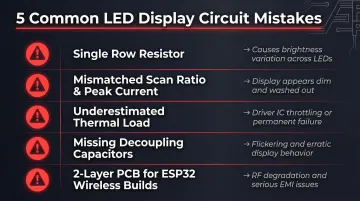
Common Mistakes When Designing LED Display Board Circuits
Even experienced designers run into these problems. Here are the five mistakes most likely to cost you a board respin:
Skip per-LED resistors and use a single row resistor instead, and brightness will shift as LEDs activate simultaneously—each additional LED pulls current from the rest, causing content-dependent dimming.
Mismatched multiplexing ratio and peak current: A 1/16 scan display gives each LED only 6.25% duty cycle. Without a proportional increase in peak current, the display looks dim. Compensating in firmware alone risks exceeding the driver IC's peak current rating.
Underestimating thermal load: Driver ICs near their thermal limit throttle or fail—usually discovered after fabrication when fixing it means a board respin. The MAX7219 datasheet specifically warns that partial scan modes (3 digits or fewer) cause excessive dissipation; increase the current-limiting resistor value accordingly.
Omitting decoupling capacitors near driver ICs: High-frequency multiplexing switching creates voltage spikes on power rails. Place 0.1µF ceramic capacitors directly at each driver IC's power pins or expect flickering and erratic behavior.
Using 2-layer PCBs for ESP32-based wireless displays: ESP32 hardware guidelines call for 4-layer boards (Signal/GND/Power/Signal) with continuous ground planes to isolate RF circuitry and suppress EMI from PWM switching. A 2-layer layout risks RF degradation and FCC compliance failures.
Frequently Asked Questions
How does an LED display board circuit work?
An LED display board uses a row-column matrix where a microcontroller activates one row at a time while setting column outputs to match the desired LED pattern. By cycling through all rows fast enough (typically 100Hz+ total refresh), the human eye perceives a continuous image rather than individual flashing rows.
Do you need a resistor for every LED in a display board circuit?
While shared row resistors work for simple circuits, per-LED resistors deliver more uniform brightness in multiplexed designs where active LED counts per row vary. Dedicated drivers like the MAX7219 handle this automatically — a single external resistor programs internal constant-current sources, keeping brightness consistent across any LED count.
Do LEDs in a display board circuit run on AC or DC current?
LEDs are polarized semiconductor devices that operate on DC current only. AC must be rectified and regulated before use. Reverse voltage above the LED's rated breakdown voltage (typically 5V) will cause immediate failure.
What microcontroller is best for an LED display board circuit?
Arduino (Uno/Nano) works well for simple wired matrix displays with limited GPIO requirements. The ESP32 is recommended for wireless and multi-panel applications due to its integrated Wi-Fi/Bluetooth, sufficient GPIO for SPI driver interfaces, and processing speed for real-time scrolling and wireless communication.
How do you add wireless control to an LED display board?
A wireless microcontroller like the ESP32 receives display content via Bluetooth or Wi-Fi and writes it to an in-memory frame buffer. The refresh loop reads from that buffer continuously, keeping wireless updates and display rendering on separate tasks so content changes never interrupt the refresh cycle.
What PCB layer count is needed for an LED display board?
Single-color or large pixel pitch displays typically need 1-2 layers; moderate-complexity designs use 2-4. High-density RGB and ESP32-based wireless displays require 4 layers minimum to manage power distribution, ground planes, and EMI at high refresh rates.