Introduction
FR4 dominates PCB manufacturing for one simple reason: it delivers the best balance of cost, reliability, and performance for the widest range of applications. From smartphones to automotive control systems, medical devices to telecommunications infrastructure, FR4 remains the default substrate choice for engineers worldwide. Yet most buyers and designers don't fully understand what makes FR4 special — or when it falls short.
This guide breaks down what you actually need to know before specifying or sourcing an FR4 board:
- FR4's composition, origins, and what "FR" actually means
- Key physical and electrical properties — and their real-world implications
- Board types FR4 supports, from single-sided to complex multilayer
- Design considerations that affect yield, reliability, and cost
- Where FR4 hits its limits and alternative materials take over
Whether you're placing your first PCB order or optimizing a complex multilayer design, you'll come away with the practical knowledge to make confident substrate decisions.
Key Takeaways
- FR4 is a NEMA-designated glass-reinforced epoxy laminate with flame-retardant properties, standardized in 1968
- Standard FR4 has a Tg of ~130–140°C; High-Tg variants reach 170–180°C for lead-free and high-temp applications
- Dielectric constant (~4.4 at 1 GHz) suits sub-GHz designs; signal loss becomes problematic above 1–2 GHz
- FR4 costs $0.10–$0.50 per square inch versus $20–$75 for PTFE alternatives — making it the default for cost-sensitive builds
- Layer counts range from 1 to 68+ layers for commercial FR4 builds, with 4–12 layers covering most applications
What Is FR4? Definition, Composition, and Origin
The NEMA Standard and 1968 Introduction
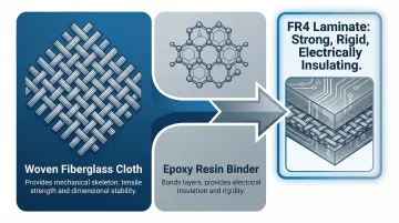
FR4 is not a generic term—it's a specific material grade established by the National Electrical Manufacturers Association (NEMA) in 1968. The designation appears in the NEMA LI 1-1998 standard (Industrial Laminated Thermosetting Products), which defines FR4 as a composite material consisting of woven fiberglass cloth bonded with an epoxy resin binder.
The "FR" stands for "flame retardant," indicating the material is self-extinguishing, while "4" identifies it within the glass epoxy laminate family. This family includes G-10, G-11, FR-4, FR-5, and FR-6, each with distinct thermal and mechanical properties.
FR4's performance comes from its two-part construction:
- Woven fiberglass cloth provides the mechanical skeleton — high tensile strength and dimensional stability
- Epoxy resin binder bonds the layers and provides electrical insulation, creating a rigid dielectric substrate
Together, these materials deliver the balance FR4 is known for: mechanically strong, structurally rigid, and electrically insulating.
The UL94V-0 Distinction
A critical procurement detail: being labeled "FR4" does not automatically guarantee UL 94 V-0 flame-retardant compliance. The NEMA designation alone does not confirm the material meets UL 94 V-0 certification — those are separate standards.
UL 94 V-0 requires vertical flame testing under UL 94 Section 8 at an accredited laboratory. Test samples must self-extinguish within 10 seconds without dripping flaming particles that ignite a cotton indicator. If regulatory compliance is required, explicitly specify UL 94 V-0 certification in your procurement documents rather than assuming the FR4 designation covers it.
FR4 vs. G-10: Why FR4 Replaced Its Predecessor
Those flame-retardant properties also explain why FR4 displaced its predecessor, G-10. Both materials share a similar glass-epoxy composite structure, but G-10 lacks self-extinguishing behavior. That single difference made FR4 the dominant standard in modern PCB production, effectively replacing G-10 across nearly all applications.
FR4's Role in PCB Construction
In PCB fabrication, FR4 serves two distinct roles:
- Core laminate (C-stage): Fully cured, rigid FR4 forms the base dielectric substrate onto which thin copper foil layers are laminated under heat and pressure
- Prepreg (B-stage): Partially cured FR4 resin layers bond inner copper layers together during multilayer lamination
Both roles are governed by IPC-4101 specifications — understanding this distinction matters when specifying laminate stack-ups for multilayer designs.
Key Physical and Electrical Properties of FR4
Mechanical Strength and Durability
FR4 exhibits robust mechanical properties that allow it to withstand assembly stresses and end-use environments. According to NEMA LI 1-1998 and manufacturer datasheets, standard FR4 delivers:
- Flexural strength (lengthwise): >415 MPa (60,200 psi)
- Flexural strength (crosswise): >345 MPa (50,000 psi)
- Rockwell hardness: 110 M scale
- Density/specific gravity: ~1.85 g/cm³
- Young's modulus (lengthwise): 3.5 × 10⁶ psi (24 GPa)
This high strength-to-weight ratio makes FR4 suitable for applications requiring durability without adding excessive mass. Mechanical performance, however, is only part of the picture — the electrical characteristics are what drive most design decisions.
Electrical Insulation Characteristics
FR4's dielectric properties determine its suitability across different signal frequencies:
| Property | Typical Value | Test Method |
|---|---|---|
| Dielectric Constant (Dk) | 3.9–4.7 (~4.4 @ 1 GHz) | IPC-TM-650 2.5.5.9 |
| Dissipation Factor (Df) | 0.017–0.030 @ 1 GHz | IPC-TM-650 2.5.5.9 |
| Dielectric Breakdown | >50 kV | IPC-TM-650 2.5.6 / ASTM D149 |
In practice, these values shape design constraints directly:
- Dielectric constant (~4.4) is the primary input for controlled-impedance calculations; variations across manufacturers can shift characteristic impedance
- Dissipation factor (~0.020) causes signal loss at higher frequencies; acceptable for sub-GHz designs but problematic above 1–2 GHz
- Dielectric breakdown (>50 kV) provides excellent high-voltage isolation when proper creepage and clearance distances are maintained
Thermal Properties
FR4's thermal behavior is critical for soldering processes and operating environments:
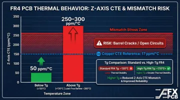
- Glass transition temperature (Tg): Standard FR4 typically exhibits Tg of 130–140°C; High-Tg variants reach 170–180°C
- Z-axis coefficient of thermal expansion (CTE): ~40–70 ppm/°C below Tg, spiking to 250–300 ppm/°C above Tg
- Thermal conductivity: 0.29–0.34 W/m·K through-plane
- Maximum continuous operating temperature (MOT/RTI): Typically 130°C per UL 796 rating
Above the glass transition temperature, FR4 softens and loses dimensional stability. During lead-free reflow (peak ~260°C), standard FR4 exceeds its Tg, causing the Z-axis CTE to spike from ~50 ppm/°C to over 250 ppm/°C.
That mismatch creates severe tensile stress against copper plating (static CTE of ~17 ppm/°C), which can crack plated through-hole barrels in thick boards or high layer counts. High-Tg FR4 is specified precisely for lead-free soldering and elevated operating environments to avoid this failure mode.
Moisture Resistance
FR4 exhibits near-zero water absorption: per IPC-TM-650 2.6.2.1 and ASTM D570 testing, absorption is <0.10% at 0.125" thickness.
This stability across dry and humid conditions is why FR4 is a standard choice for industrial, marine, and outdoor applications where moisture exposure is a real concern.
Types of FR4 PCBs
FR4 enables five main board configurations, each suited to different complexity and performance requirements.
| Board Type | Key Characteristic | Common Applications |
|---|---|---|
| Single-Sided | Copper on one side only; lowest cost | Consumer electronics, LED lighting, basic power supplies |
| Double-Sided | Copper on both surfaces; through-hole plating links layers | Mid-complexity assemblies using through-hole and SMT components |
| Multilayer | 3+ conductive layers laminated under pressure; FR4 prepreg bonds inner layers | High-density designs requiring tightly controlled impedance |
SFX PCB manufactures FR4 multilayer boards from 4 to 68 layers, though most commercial designs fall between 4 and 12 layers.
Rigid vs. Rigid-Flex FR4 PCBs
Rigid FR4 boards are the most common form factor, used where no bending is required. These boards maintain their shape throughout the product lifecycle and are suitable for the vast majority of applications.
Rigid-flex designs combine FR4 structural sections with flexible polyimide material, enabling three-dimensional installation in compact enclosures. Eliminating connectors between rigid and flexible sections directly reduces potential failure points. SFX PCB manufactures rigid-flex boards for:
- Medical devices — defibrillators, ultrasound equipment
- Aerospace systems — radars, night vision hardware
- Automotive electronics — dashboards, ABS control units
High-Tg FR4
Standard FR4 has a Tg of approximately 130–140°C, while High-Tg FR4 variants reach 170–180°C. The higher glass transition temperature delays the onset of rapid Z-axis expansion during thermal cycling.
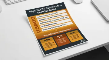
When to specify High-Tg FR4:
- Lead-free soldering reflow profiles (peak ~260°C)
- Automotive applications with sustained elevated temperatures
- Multilayer boards >6 layers or thickness >0.062"
- IPC Class 3 high-reliability assemblies
- Any environment with continuous operating temperatures above 130°C
Once you've identified which criteria apply, matching the grade to the requirement keeps material costs in check. SFX PCB offers High-Tg FR4 in three ratings — Tg150 (150°C), Tg170 (170°C), and Tg180 (180°C or above) — so designers can align material performance to actual thermal demands without unnecessary material costs.
Advantages of FR4 PCBs
Unbeatable Cost-Performance Balance
FR4's market dominance stems from its economic efficiency. Standard FR4 costs $0.10–$0.50 per square inch, while high-frequency PTFE/Rogers laminates command $20–$75 per square inch—approximately 40 to 150 times the cost. According to Prismark's 2023 market update, the rigid PCB industry consumed approximately $13 billion of copper-clad laminates, with FR4 driving the vast majority of conventional volume. This massive price advantage makes FR4 the default choice for cost-sensitive designs across consumer, industrial, and medical sectors.
Processing Versatility
FR4 is compatible with standard PCB fabrication processes:
- Drilling, etching, and plating using conventional equipment
- Both through-hole and SMT assembly without special handling
- Wide range of thicknesses (SFX PCB offers 0.1mm to 8mm)
- Multiple copper weights (SFX PCB provides 1oz to 10oz per layer)
- Standard surface finishes including HASL, lead-free HASL, ENIG, immersion silver, immersion tin, hard gold, and OSP
This universal fabricator familiarity reduces sourcing complexity and manufacturing friction, cutting lead times and production risk.
Reliability Under Real-World Conditions
FR4 maintains its structural and electrical properties across a wide ambient temperature range, with near-zero moisture absorption (<0.10%) adding resilience against humidity and thermal cycling. Key ratings at a glance:
- Standard FR4: UL 796 rated for continuous operation at 130°C
- High-Tg FR4: Sustains temperatures up to 180°C for higher-heat applications
- Moisture absorption: <0.10%, limiting warping and delamination risk
These properties make FR4 a dependable substrate in sectors where field failures are not an option — automotive control units, medical diagnostics, and telecommunications infrastructure among them. SFX PCB holds ISO 9001, ISO 14001, and ISO 13485 certifications and has supplied FR4 boards across these industries for over 15 years, from prototype quantities through full production runs.
FR4 PCB Design Considerations
Layer Stackup Planning
Choosing the number of layers and their sequence determines signal integrity, power distribution, and EMI shielding. Symmetrical stackups prevent warpage during FR4 lamination by balancing CTE forces around the board's center core.
The two most common configurations:
| Configuration | Layer Order | Key Benefit |
|---|---|---|
| 4-layer (most popular) | Signal / Ground / Power / Signal | Reduces loop area and inductance, lowering noise and controlled radiation |
| 6-layer | Signal / Plane / Signal / Signal / Plane / Signal | Ensures well-matched impedance throughout the entire stackup |
SFX PCB provides stackup recommendations as part of its free DFM review, covering both signal integrity and manufacturability.
Trace Width, Spacing, and Impedance Control
FR4's dielectric constant (~4.4) is the primary input into controlled-impedance calculations per IPC-2141A formulas. However, Dk is not a static value—it varies significantly (3.9 to 4.7) based on glass weave style (such as 1080 vs. 7628) and resin content.
Request the actual Dk value from your fabricator's material datasheet rather than using generic catalog values. This ensures impedance calculations account for the resin and glass weave effects specific to your board construction.
Thermal Management
FR4's low through-plane thermal conductivity (0.29–0.34 W/m·K) means heat must be managed through design choices rather than through the substrate itself:
- Thermal vias to conduct heat from components to ground planes
- Heavy copper pours to spread heat across larger areas
- Heat sinks attached to high-power components
- Metal-core PCBs (20–200 W/m·K) for extreme heat applications
This is a critical consideration in power electronics, LED applications, and high-performance computing where component heat dissipation drives design decisions.
Design for Manufacturability (DFM)
Common FR4-specific DFM issues include:
- Minimum drill-to-copper clearances to prevent shorts during drilling
- Controlled-depth drilling for blind/buried vias
- Copper balance across layers to prevent bow and twist during lamination
- Annular ring compliance to ensure via integrity
- Asymmetric stackup violations that cause warpage
Catching these issues before production begins prevents rework costs and delays. SFX PCB's engineering team reviews new file submissions within 12 hours, flagging DFM issues and recommending fixes to improve yield.
When FR4 Falls Short: Limitations and Alternatives
High-Frequency Signal Degradation
FR4's dissipation factor (~0.020–0.030) causes significant signal loss at RF and microwave frequencies. Above 1–2 GHz, FR4's dielectric loss degrades signal integrity to the point where alternative materials become necessary.
FR4 vs. PTFE Performance Comparison:
| Metric | Standard FR4 | Rogers RO4003C |
|---|---|---|
| Dk @ 10 GHz | ~4.2–4.5 (unstable) | 3.38 ± 0.05 (stable) |
| Df @ 10 GHz | ~0.025 | 0.0027 |
| Cost Multiplier | 1x baseline | 40x–150x premium |
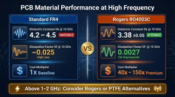
For 5G, radar, satellite communications, and applications above 10 GHz, PTFE-based laminates like Rogers RO4003C are mandatory to preserve signal-to-noise ratios. That cost premium is significant, so engineers often use hybrid stackups — placing Rogers material only on outer RF layers while keeping FR4 for inner power/logic cores.
SFX PCB manufactures Rogers PCBs using RO4003C and RO4350B materials, along with PTFE (Teflon) substrates for demanding high-frequency applications where FR4's higher dielectric loss would degrade signal performance.
Extreme Temperature Environments
Standard FR4 is not recommended for applications that exceed its Tg or require sustained operation above approximately 130°C. In such cases, alternatives should be evaluated:
- High-Tg FR4 (170–180°C) for automotive and industrial applications
- Polyimide substrates for flexible circuits requiring elevated temperature tolerance
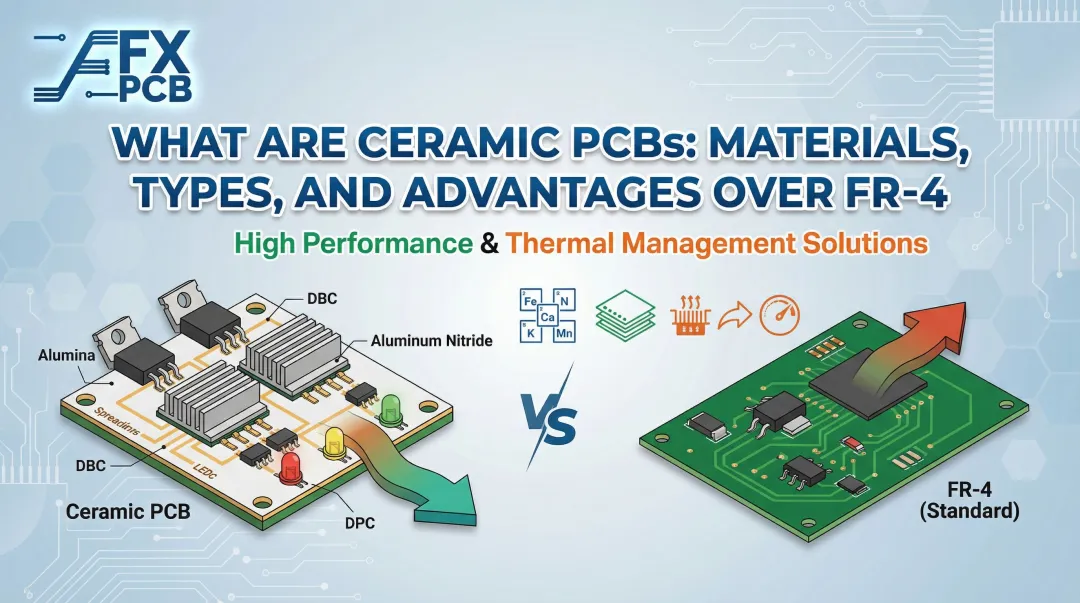
- Ceramic-based materials (ALN, Al₂O₃) with thermal conductivity up to 170 W/(m·K) for extreme heat applications
Lead-Free Soldering Reflow Risk
FR4's Z-axis CTE (~50–70 ppm/°C below Tg) is significantly higher than copper (~17 ppm/°C). When board temperature exceeds Tg during lead-free reflow (peak ~260°C), the Z-axis CTE spikes to 250–300 ppm/°C, exerting extreme tensile stress on plated through-holes. This can cause barrel cracks and intermittent open circuits.
For high-reliability or IPC Class 3 assemblies, engineers should specify High-Tg FR4 or alternative substrates with lower CTE. SFX PCB offers High-Tg FR4 variants (Tg150, Tg170, Tg180) specifically to address this challenge in multilayer boards and lead-free assembly processes.
Guidance on Substrate Selection
Selecting the right substrate involves weighing frequency, thermal, reliability, and cost requirements together. SFX PCB's engineering team supports customers across FR4, High-Tg, and specialty material builds — including Rogers, PTFE, polyimide, ceramic, and hybrid solutions — helping teams choose the right material for their application without over-specifying into unnecessary cost tiers. Contact their technical support team for material selection consultation tailored to your specific design requirements.
Frequently Asked Questions
What is an FR4 printed circuit board?
An FR4 PCB is a printed circuit board whose base substrate is made from woven fiberglass cloth bonded with flame-retardant epoxy resin. It's the industry's most widely used laminate material due to its balance of electrical insulation, mechanical strength, and cost-effectiveness.
Are G10 and FR4 the same PCB material?
G-10 and FR4 share a similar glass-epoxy composite structure but differ in one critical way: FR4 incorporates a flame-retardant additive (typically bromine-based) that makes it self-extinguishing, while G-10 is not flame retardant. As a result, FR4 has largely replaced G-10 in modern PCB production.
Is an FR4 printed circuit board electrically conductive?
The FR4 substrate itself is an electrical insulator with high dielectric strength (>50 kV dielectric breakdown), meaning it does not conduct electricity. Conductivity on a PCB comes entirely from the copper foil layers laminated onto the FR4 base.
What is the glass transition temperature of FR4, and why does it matter?
Standard FR4 has a Tg of approximately 130–140°C; High-Tg variants reach 170–180°C. Above that threshold, the material softens and loses dimensional stability — making High-Tg FR4 the right choice for lead-free soldering processes and environments where thermal cycling stresses plated through-holes.
What are the main alternatives to FR4 for high-frequency PCB designs?
PTFE/ceramic-filled laminates (such as Rogers RO4003C and Taconic laminates) and polyimide are the primary alternatives. They offer significantly lower loss tangents (Df ~0.0027 vs. ~0.025 for FR4) suited to RF, microwave, and 5G applications where FR4's higher dielectric loss would degrade signal performance.
How many layers can an FR4 PCB have?
FR4 PCBs can be manufactured with anywhere from 1 to 68+ layers, though most commercial designs fall between 2 and 12. Layer count is constrained by cost, manufacturing precision, and the minimum achievable thickness between layers.