The LED aluminum PCB solves this problem. By using an aluminum alloy base as its substrate, this specialized metal core PCB efficiently transfers heat away from LED components, keeping junction temperatures low and performance stable.
This guide covers the definition, three-layer construction, key benefits, substrate comparisons, and real-world applications of LED aluminum PCBs—plus what to look for when sourcing them.
What Is an LED Aluminum PCB?
An LED aluminum PCB is a metal core printed circuit board (MCPCB) that uses an aluminum alloy base as its substrate. It's specifically designed to mount LED components and efficiently transfer the heat they generate away from the circuit.
Unlike standard PCBs that use fiberglass (FR-4) as the base, LED aluminum PCBs use metal as the foundation. This gives them far superior thermal management properties—critical for high-power LED arrays where heat buildup directly impacts performance and longevity.
That thermal substrate structure is also what earns them the name Insulated Metal Substrate (IMS) boards. Among all MCPCB variants, aluminum versions remain the most widely used for LED lighting — balancing thermal performance, mechanical strength, and cost.
Key Takeaways
- LED aluminum PCBs use an aluminum base to dissipate heat generated by LEDs
- They are a category of Metal Core PCB (MCPCB), also known as Insulated Metal Substrate (IMS)
- Three layers: copper circuit layer, thermally conductive dielectric layer, aluminum base
- Most common and cost-effective solution for LED lighting applications
- Thermal conductivity reaches 1–4 W/m·K vs. ~0.3 W/m·K for FR-4 — directly extending LED lifespan
How an LED Aluminum PCB Is Constructed
LED aluminum PCBs use a three-layer sandwich structure. Each layer handles a specific job — thermal transfer, electrical isolation, or structural support — and the combination is what makes these boards effective for high-power LED applications.
The three layers are:
- Copper circuit layer (top)
- Thermally conductive dielectric layer (middle)
- Aluminum base layer (bottom)
Copper Circuit Layer
The copper foil layer is the topmost layer where LED components and circuit traces are etched. This is where SMD LED pads and circuit connections are formed.
Typical copper weights used in LED applications include:
- 1 oz (35 µm): Standard commercial LED lighting and general routing
- 2 oz (70 µm): High-power LED drivers and automotive electronics handling 1-10A currents
- 3 oz (105 µm): Extreme power electronics and dense COB arrays
Heavier copper can carry higher currents for high-power LEDs. According to IPC-2152 guidelines, traces on MCPCBs can carry significantly higher currents than identical traces on FR-4 because the thermally conductive dielectric rapidly pulls heat away from the copper circuit.
Thermally Conductive Dielectric Layer
Unlike standard FR-4, which traps heat at the circuit layer, the aluminum PCB uses a thin polymer or ceramic-filled dielectric bonded between the copper circuit and the aluminum base. It blocks electrical current while conducting heat downward — which is precisely what makes aluminum PCBs viable for high-power LEDs.
Thermal conductivity values:
- Standard grades: 1.0–2.0 W/m·K
- Premium grades: 2.0–3.0+ W/m·K
- Ultra-high grades: 4.0–8.0 W/m·K
For comparison, standard FR-4 offers only 0.3–0.4 W/m·K—meaning even standard aluminum PCB dielectrics are 3-5x more thermally conductive.
The thickness and material quality of this layer directly determine the board's overall thermal resistance. A thinner, higher-conductivity dielectric means faster heat transfer to the aluminum base. Typical thicknesses run from 38 µm to 200 µm — thinner layers improve thermal performance but require tighter process control during lamination.
Aluminum Base Layer
The aluminum base is the bottom structural layer that gives the board its rigidity, serves as a heatsink, and draws heat away from the dielectric and circuit layer.
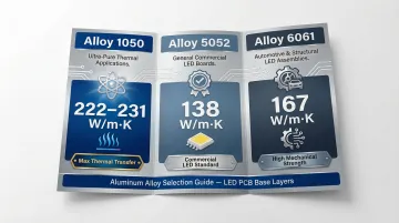
Common aluminum alloys include:
| Alloy | Thermal Conductivity (W/m·K) | Characteristics |
|---|---|---|
| 1050 | 222–231 | 99.5% pure aluminum. Soft, poor machinability, but maximum thermal transfer. Best for simple shapes. |
| 5052 | 138 | Alloyed with magnesium. Medium strength, good formability. Industry standard for commercial LED lighting. |
| 6061 | 167 | Alloyed with silicon/copper. Hard, excellent machinability. Best for high mechanical stress and automotive applications. |
Typical base thicknesses range from 1.0 mm to 3.0 mm, with 1.0 mm and 1.5 mm being the most common for standard LED lighting. Thicker bases add structural rigidity and heatsinking capacity for demanding environments.
Individual LEDs are too small to accept external heatsinks, and any attached heatsink would physically block emitted light. The aluminum base solves this by acting as an integrated thermal management system built directly into the board structure.
Key Benefits of LED Aluminum PCBs for Lighting Applications
The benefits of LED aluminum PCBs build on each other. Better heat dissipation enables longer lifespan, which supports reliability, which justifies the design investment.
Key benefits include:
- Superior heat dissipation
- Extended LED lifespan and reliability
- Mechanical strength and dimensional stability
- Lightweight and cost-effective
- Design flexibility
Superior Heat Dissipation
The board's core advantage is rapid heat removal from LED junctions.
FR-4 typically has thermal conductivity of ~0.3 W/m·K, while aluminum PCB dielectric layers offer 1–3+ W/m·K. This represents a 3-10x improvement in thermal performance.
Research shows that metal-embedded PCBs can reduce total thermal resistance by up to 65.60% and junction temperature by 56.25% compared to standard FR-4.
Lower LED junction temperatures directly translate to stable lumen output and reduced thermal degradation.
Extended LED Lifespan and Reliability
Heat is the leading cause of LED degradation. Elevated junction temperatures accelerate lumen depreciation and can cause color shift.
By transferring heat to the aluminum base, aluminum PCBs keep junction temperatures lower, which extends operational lifespan.
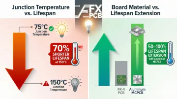
Doubling the junction temperature of an LED from 75°C to 150°C can shorten its life by more than 70 percent. Conversely, maintaining lower junction temperatures through metal core PCBs can extend LED lifespan by 50–100% versus equivalent FR-4 boards.
Mechanical Strength and Dimensional Stability
The aluminum substrate provides structural rigidity that FR-4 cannot match at similar thicknesses, making it suitable for applications with vibration, shock, or thermal cycling.
Aluminum alloys have a coefficient of thermal expansion (CTE) of 23.6–23.8 ppm/°C. While this is higher than FR-4 (13–14 ppm/°C), premium IMS dielectrics are formulated with a low modulus to absorb CTE mismatch stresses between the substrate and ceramic LED packages.
This prevents board warpage under repeated heating and cooling cycles, which matters most in automotive and outdoor fixtures that face extreme temperature swings.
Lightweight and Cost-Effective
Aluminum achieves a balance of lightweight construction with adequate thermal performance, making it the most cost-effective MCPCB choice.
Weight comparison:
- Aluminum density: ~2.70 g/cm³
- Copper density: ~8.96 g/cm³
Using an aluminum core offers a weight reduction of nearly 66% compared to a copper core of the same dimensions.
Cost comparison:
While copper core offers higher thermal conductivity (~385–400 W/m·K vs. aluminum's 138–231 W/m·K), copper is 3.3x heavier and commands a 300–400% cost premium. Finished copper-core MCPCBs typically cost 2.5 to 3.5 times more than equivalent aluminum boards.
Most commercial LED applications use aluminum precisely because the material cost is low and thermal performance is more than sufficient.
Design Flexibility
Aluminum PCBs can be manufactured in custom shapes, sizes, and configurations—round, rectangular, strip formats—to suit different LED lighting fixture designs.
They are compatible with standard SMD LED components and can integrate multiple LEDs of different color temperatures on a single board, enabling color tuning and varied light output from one assembly.
LED Aluminum PCB vs. Other PCB Substrate Types
Understanding when to choose aluminum over other substrates helps optimize both performance and cost.
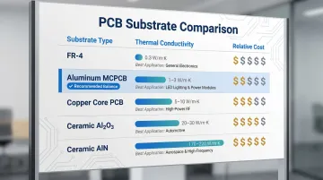
| Substrate Type | Thermal Conductivity | Relative Cost | Best Application |
|---|---|---|---|
| FR-4 LED PCB | 0.3–0.4 W/m·K | Lowest | Low-power indicators, basic consumer electronics |
| Aluminum MCPCB | 1.0–8.0 W/m·K (dielectric) | Low-Medium | General LED lighting, automotive DRLs, street lights |
| Copper Core PCB | 385–400 W/m·K (core) | High (3x Al) | Extreme power density (>2 W/cm²), automotive headlights |
| Ceramic PCB (Al₂O₃) | 20–30 W/m·K | High | High-end RF, sensors, specialized power modules |
| Ceramic PCB (AlN) | 140–180 W/m·K | Very High | UV-LEDs, laser systems, extreme thermal cycling |
Each substrate fills a specific niche based on power density and budget:
- FR-4 is cost-effective but thermal-limited — fine for indicator LEDs, inadequate once heat becomes a design constraint
- Copper core closes the performance gap when aluminum falls short, but at roughly 3x the cost and added weight
- Ceramic (Al₂O₃ / AlN) suits extreme-reliability scenarios like UV-LEDs and laser drivers where electrical isolation is as critical as heat dissipation
For most commercial LED applications — street lights, panel lights, automotive DRLs, bulbs — aluminum MCPCB hits the right crossover point: thermal conductivity high enough to protect the LED, cost low enough to scale production.
Where LED Aluminum PCBs Are Used: Key Applications
LED aluminum PCBs are found wherever efficient, reliable LED lighting is required—spanning consumer, industrial, commercial, and specialized sectors.
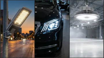
General and Commercial Lighting
Applications include LED bulbs, downlights, panel lights, street lights, and high-bay industrial lighting.
Managing heat from arrays of multiple high-power LEDs is essential for maintaining consistent lumen output and meeting rated lifespan. In continuous-use environments, thermal performance is what separates a lighting fixture that hits its rated lifespan from one that fails early.
Automotive Lighting
Automotive applications include headlights, brake lights, turn indicators, and interior accent lighting. Aluminum PCBs suit this environment because they handle:
- Extreme temperature cycling from cold starts to sustained highway driving
- Constant mechanical vibration without solder joint fatigue
- Compact packaging within tight headlamp assemblies
Medical and Specialized Lighting
Surgical lighting, medical examination lamps, and diagnostic equipment all demand consistent high-intensity output over long operational periods. Aluminum PCBs meet this requirement while also serving medical scanning equipment where precise thermal control directly affects measurement accuracy.
Telecommunications and Electronics
LED indicators and display backlights in telecommunications equipment and computing hardware rely on aluminum PCBs to protect adjacent heat-sensitive components. Without effective thermal dissipation, LED arrays running continuously in sealed housings risk triggering thermal runaway that degrades surrounding circuitry.
These applications collectively reflect significant market momentum: the global metal core PCB market was valued at $13.7 billion in 2023 and is projected to grow at a CAGR of over 4% through 2032, driven by the shift toward energy-efficient LED lighting and expansion of smart and automotive lighting segments.
What to Look for When Sourcing LED Aluminum PCBs
When sourcing LED aluminum PCBs, confirm these key technical specifications with your manufacturer:
- Dielectric thermal conductivity (W/m·K): Standard dielectric layers run 1–2 W/m·K — adequate for general lighting. High-power dense arrays need 2–3+ W/m·K; specify this explicitly with your manufacturer.
- Copper weight: 1 oz for standard lighting, 2-3 oz for high-power applications
- Aluminum alloy grade: 5052 for standard routing/punching, 6061 for high mechanical strength
- Board thickness: 1.0 mm and 1.6 mm are most common; thicker bases add rigidity and heatsinking capacity
- Surface finish: HASL, ENIG, and OSP are all available. ENIG is the preferred choice for fine-pitch SMD LED pads — its flat surface and consistent solderability reduce pad defects at scale.
- Compliance: RoHS and REACH standards for global market access
Design for Manufacturability (DFM) Analysis
Work with a manufacturer that offers DFM analysis before production begins. This step catches thermal design issues, via placement problems, and pad sizing errors before they become costly rework.
SFX PCB runs free DFM analysis on every order and performs 100% electrical testing on all bare boards. The company holds ISO9001, ISO14001, and ISO13485 certifications — covering quality management, environmental responsibility, and medical-grade production standards.
Prototyping and Scaling Capability
Fast-turnaround prototyping is valuable when iterating on LED lighting designs. Look for a manufacturer that scales from prototype to high-volume production without a supplier change or re-qualification costs.
SFX PCB handles orders from prototype batches of 5 pieces up to full mass production volumes. Single-sided aluminum PCB prototypes ship in 5 working days; double-sided prototypes in 14 working days.
Frequently Asked Questions
What is the difference between an LED aluminum PCB and a standard FR-4 LED PCB?
FR-4 uses a fiberglass-epoxy base with low thermal conductivity (~0.3 W/m·K), making it adequate only for low-power LEDs. Aluminum PCB uses an aluminum base with a thermally conductive dielectric layer that transfers heat far more efficiently, making it the standard choice for medium- to high-power LED arrays.
Can LED aluminum PCBs be made double-sided or multilayer?
Most LED aluminum PCBs are single-sided — routing electrical connections through a metal base layer is inherently difficult. Double-sided versions are possible but more complex and costly to manufacture, used only when circuit density exceeds what a single-sided design can support.
What thermal conductivity should I look for in an LED aluminum PCB?
Standard dielectric layers offer around 1–2 W/m·K, sufficient for most general lighting applications. For high-power LED applications with dense arrays or demanding thermal environments, premium dielectric materials with 2–3+ W/m·K thermal conductivity should be specified.
How thick is the aluminum base layer typically used in LED PCBs?
Aluminum base thickness typically ranges from 1.0 mm to 3.0 mm, with 1.0 mm and 1.6 mm being the most common for standard LED lighting. Thicker bases are used when greater structural rigidity or additional heatsinking capacity is needed.
Are LED aluminum PCBs RoHS and REACH compliant?
Yes — LED aluminum PCBs can be manufactured fully RoHS and REACH compliant, which is required for products sold in European and other regulated markets. Confirm compliance certifications and request documentation before placing your order.
What surface finishes are available for LED aluminum PCBs?
Common options include:
- HASL (Hot Air Solder Leveling) — cost-effective general-purpose finish
- ENIG (Electroless Nickel Immersion Gold) — preferred for fine-pitch SMD LED pads due to its flat surface and reliable solderability
- OSP (Organic Solderability Preservative) — suitable for simpler, cost-sensitive designs