DOB (Driver-on-Board) LED PCBs resolve this tension by integrating the driver circuit directly onto the same board as the LED array, eliminating the need for a separate external driver module entirely. The result is a self-contained, mains-ready module that connects directly to AC power.
This guide covers everything engineers and product designers need to know about DOB LED PCB technology: how the circuit works, where it fits versus COB and SMD architectures, substrate selection, and the design constraints that determine whether DOB is the right call for a given application.
Key Takeaways
- DOB (Driver-on-Board) integrates the LED driver circuit directly onto the same PCB as the LED array, eliminating the need for a separate external driver
- DOB is a power delivery design approach, not a chip mounting technology—it's a different category from COB and SMD
- Core advantages: reduced BOM cost, compact form factor, simpler installation without external driver wiring
- Core disadvantages: thermal accumulation from shared board, reduced serviceability, limited native dimming support
- Aluminum MCPCB is the preferred substrate for most DOB designs, given its thermal management properties
- Typical applications: LED replacement bulbs, panel lights, tube lights, ceiling fixtures, and low-wattage outdoor lighting
What Is a DOB LED PCB?
DOB stands for Driver-on-Board. It means the electronic driver circuit that regulates voltage and current to the LED array is integrated directly onto the same printed circuit board as the LEDs themselves. There's no separate AC-to-DC converter module, no external driver enclosure, and no additional wiring harness.
The board connects directly to AC mains voltage (commonly 110 V or 220 V, though Seoul Semiconductor's Acrich product family supports a broader range including 55 V, 100 V, 120 V, 230 V, 240 V, and 277 V in direct-AC configurations). The driver circuitry on the board handles rectification, filtering, and current regulation internally.
Key Components on a DOB LED PCB
A typical DOB board integrates all of the following onto a single substrate:
- LED chip array (SMD or COB-style emitters)
- Bridge rectifier converts incoming AC to DC
- Filter capacitors smooth the rectified voltage
- Constant-current IC or regulator maintains stable LED current
- Surge and overvoltage protection components (TVS diodes, resistors)
- Output regulation circuit
One distinction worth clarifying: DOB is a PCB circuit design philosophy, not a chip mounting technology. COB (Chip-on-Board) and SMD (Surface-Mount Device) describe how LED chips are physically placed on a board. DOB describes how power is delivered to those chips. A DOB board can use SMD chips as its LED array — these aren't mutually exclusive categories.
Traditional Driver Setup vs. DOB
In a conventional LED lighting system, a standalone AC-to-DC driver converts mains voltage to regulated DC, then feeds that DC to the LED board via wiring and connectors. That means two separate components in two separate housings, which multiplies potential failure points.
With DOB, the entire conversion and regulation process moves onto the LED board itself. The key differences:
- Conventional setup: External driver module + LED board + wiring + connectors
- DOB setup: Single board handles AC input, rectification, regulation, and light output
- Size impact: Eliminates bulky electrolytic capacitors, inductors, and transformers
The Acrich3 105W datasheet from Seoul Semiconductor documents how this integration reduces board footprint and enables slimmer fixture profiles. An IEEE 2023 study on direct-AC LED drivers reported a total module thickness of just 8.15 mm including the aluminum substrate.
How the DOB LED Driver Circuit Works
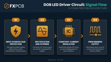
DOB boards process AC mains power through four functional stages before it reaches the LEDs.
Stage 1: Input Overvoltage Protection
When AC enters the board, protection components (typically TVS diodes and current-limiting resistors) clamp voltage spikes from lightning strikes or mains fluctuations before they reach downstream circuitry. The Acrich3 105W design includes TVS diodes in its BOM for this function.
Without adequate protection, electrical overstress causes either immediate catastrophic LED failure or latent degradation that surfaces hundreds of operating hours later.
Stage 2: Rectification and Filtering
A bridge rectifier converts the incoming AC to DC. The Acrich3 105W uses a 600 V bridge diode for this stage. Ceramic capacitors (X7R type in the Acrich3 design) then filter the resulting ripple voltage to deliver a stable DC supply to the LED array. This stage may also include polarity protection to prevent reverse-connection damage during installation.
Stage 3: Constant-Current Regulation
LEDs require stable current (not stable voltage) to maintain consistent brightness and lifespan. Two approaches exist:
- Resistor-based limiting: simple, low cost, but doesn't compensate for voltage or temperature variation
- Constant-current IC regulation: preferred for most designs; compensates for input fluctuations and temperature shifts to protect LED lifespan
The Acrich3 105W uses seven DT3007C ICs (120 Vac version) or seven DT3007B ICs (220 Vac version) for constant-current control. Diodes Incorporated's AL5809 shows what dedicated IC regulation can deliver: a 60 V two-terminal constant-current driver with 20 ppm/°C temperature stability — tight enough for demanding commercial lighting applications.
Stage 4: PWM Dimming (Where Implemented)
Pulse Width Modulation adjusts LED brightness by varying the duty cycle of the current signal rather than reducing its magnitude. According to Texas Instruments' LED driver application note, PWM dimming applies full LED current at a reduced duty cycle: at 50% brightness, the LED receives full rated current but switches on and off at half the cycle period. ROHM reports dimming ratios up to 20,000:1 at 100 Hz achievable with PWM control.
Not all DOB designs include PWM dimming natively. Adding it requires extra circuitry, which partially offsets the integration savings that make DOB attractive in the first place. Understanding these tradeoffs is essential when selecting or specifying a DOB board for a given application.
DOB LED PCB Advantages and Disadvantages
Advantages
DOB designs offer three concrete advantages for constrained or cost-sensitive applications:
- Space savings: Eliminating the external driver enclosure and wiring harness meaningfully shrinks the footprint — critical for A19 bulbs, panel lights, and tube lights where internal space is tight.
- Lower BOM cost: Fewer components, connectors, and housing parts. Seoul Semiconductor's Acrich documentation shows that DOB integration removes numerous SMPS driver components, simplifying both the circuit and manufacturing process.
- Simpler installation: The board connects directly to mains voltage with no separate driver wiring or configuration, removing a common connector failure point.
The trade-offs are real, though, and worth understanding before committing to a DOB design.
Disadvantages
Thermal accumulation is the primary challenge. The driver circuitry and LED array share the same board and generate heat simultaneously. Lumileds specifies a maximum LED junction temperature of 120°C and a maximum aluminum-core PCB temperature of 105°C for their LUXEON series. Exceeding these thresholds degrades luminous efficiency and accelerates LED wear. Substrate selection and thermal layout are essential — not optional.
High-wattage applications require careful design. DOB designs can reach high power levels — Seoul Semiconductor's Acrich range spans 4.3 W to 200 W, with the Acrich3 105W as a documented example. Thermal concentration rises with wattage, and so does the design burden. Most commodity DOB products target lower power ranges precisely because thermal management is more tractable there.
Full board replacement on driver failure. With an external driver, failure means swapping one component. With DOB, driver failure typically means replacing the entire board. The Zhaga consortium flags this directly in its work on repairable, upgradeable LED luminaires — the cost and sustainability implications are real.
Limited native dimming. Standard DOB circuit designs don't include dimming out of the box. When dimming is required, PWM circuitry must be added—partially eroding the simplicity and cost advantages that make DOB attractive in the first place.
DOB vs COB vs SMD LED: Key Differences and When to Choose Each
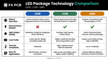
The most common confusion in LED product design is treating DOB, COB, and SMD as competing technologies in the same category — but they describe different things entirely. DOB is a power delivery architecture, while COB and SMD are emitter packaging approaches. A product can, and often does, combine DOB driver electronics with SMD LEDs on the same board.
Lumileds defines COB as many LED chips mounted on a thermally efficient substrate under a uniform phosphor coating, creating a single dense emitter. SMD packages each chip individually with its own leadframe, phosphor, and lens. DOB says nothing about the emitter—it only describes how power reaches it.
The table below maps each technology against the criteria that matter most during product design and procurement decisions.
Comparison Table
| Feature | DOB | COB | SMD |
|---|---|---|---|
| What it describes | Power delivery architecture | Chip mounting / emitter packaging | Chip mounting / emitter packaging |
| External driver needed? | No | Yes | Yes |
| Light output quality | Depends on LEDs used | Uniform, shadow-free, high intensity | Distributed; potential glare without diffuser |
| Cost profile | Lower system cost (fewer components) | Higher (dense array + separate driver) | Low per-chip cost; driver adds cost |
| Thermal complexity | High (driver + LEDs share board) | Moderate (LEDs only, driver separate) | Moderate |
| Best fit | Bulbs, panels, tubes, low-power fixtures | Spotlights, downlights, retail, industrial | Strips, displays, decorative, RGB |
Decision Framework
- Choose DOB when compactness, BOM cost reduction, and plug-and-play installation matter most—consumer replacement bulbs, panel lights, tube lights
- Choose COB when high intensity, uniform light distribution, and thermal separation between driver and emitter are priorities—spotlights, track lighting, downlights, industrial fixtures
- Choose SMD when design flexibility, RGB color mixing, or distributed light patterns are the primary requirement—LED strips, signage, architectural lighting
Common Applications of DOB LED PCBs
Indoor and Residential
DOB's compact, single-board design suits a range of common fixtures:
- LED replacement bulbs (A19 and omnidirectional form factors) — Seoul Semiconductor specifically designed the Acrich module for A19 retrofit lamps
- Panel lights and ceiling lights — flat form factor aligns well with integrated driver boards
- T8/tube lights — linear design benefits from DOB's reduced component count
- Wall lamps — space constraints in luminaire housing favor the single-board approach
Outdoor and Commercial
DOB works well for lower-wattage outdoor applications, including:
- Garden lights and landscape lighting
- Low-wattage street lamp variants
- Decorative outdoor fixtures with space-constrained housings
The Acrich family's direct-AC capability covers global mains voltages from 55 V through 277 V, making these designs viable across different regional power standards without additional conversion circuitry.
That said, higher-wattage outdoor fixtures — high-bay industrial lights and high-power floodlights — are a different story. At those power levels, the thermal separation an external driver provides outweighs the board-integration savings DOB offers.
The Acrich3 105W does list factory ceiling lights, industrial lighting, and high-bay/low-bay fixtures as supported applications. These are viable, but they represent more complex DOB implementations requiring careful thermal management.
PCB Substrate and Design Considerations for DOB LED Boards
Substrate selection drives DOB thermal performance more than almost any other design variable. The driver circuitry and LED array both generate heat on the same board—the substrate has to handle both simultaneously.
Substrate Options
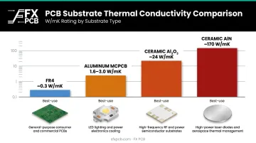
| Substrate | Thermal Conductivity | Best Use |
|---|---|---|
| Standard FR4 | ~0.3 W/mK | Very low power only |
| Aluminum MCPCB | 1.6–3.0 W/mK (dielectric layer) | Most DOB applications |
| Ceramic (Al2O3) | ~24 W/mK | High thermal demand |
| Ceramic (AlN) | ~170 W/mK | Highest thermal demand / harsh environments |
Aluminum MCPCB is the standard choice for most DOB designs. The aluminum base dissipates heat up to 9x faster than standard FR4—a meaningful difference when the LED array and driver ICs are both contributing to thermal load.
SFX PCB's aluminum MCPCB supports dielectric layer thicknesses from 50 µm to 200 µm (tuning the balance between thermal resistance and electrical insulation), copper weights from 35 µm to 210 µm (1 oz to 6 oz), and board thicknesses from 0.5 mm to 5.0 mm.
For ceramic substrates, SFX PCB manufactures both Al2O3 (≥24 W/m·K) and AlN (≥170 W/m·K) options, with the latter suitable for high-power LED modules where the thermal performance gap between aluminum MCPCB and ceramic becomes design-critical.
Key Layout Considerations
When laying out a DOB LED PCB, engineers should address:
- Place thermal vias under driver ICs and LED pads to move heat efficiently to the metal core
- Size copper weight for traces carrying mains-level or high-LED-current loads (minimum trace/space on aluminum MCPCB: 0.1 mm/0.1 mm)
- Distribute high-dissipation components across the board to avoid localized hot spots
- Maintain safety clearances between mains-voltage traces per IEC 61347-2-13:2024 and IEC 60598-1:2020
- Specify drilled holes at 0.6 mm minimum diameter on aluminum MCPCB
Every SFX PCB order includes free DFM analysis, where engineers review layouts for manufacturing and reliability issues before production begins. This, combined with IPC-A-610 Class 2/3 assembly standards, AOI, X-ray inspection, and functional testing, gives DOB LED teams a clear path from prototype to volume production without hidden rework costs.
For turnkey DOB PCBA, SFX PCB's sourcing team handles complete BOM procurement across all key components:
- Bridge rectifiers and filter capacitors
- Constant-current driver ICs
- TVS protection components
This is backed by over 15 years of LED PCB manufacturing experience across consumer, commercial, and industrial lighting segments.
Frequently Asked Questions
What is DOB in LED?
DOB stands for Driver-on-Board. The LED driver circuit—which regulates voltage and current to the LEDs—is integrated directly onto the same PCB as the LED array. This eliminates the need for a separate external driver module and allows the board to connect directly to AC mains voltage.
What is the difference between DOB and COB LED lights?
DOB describes a power delivery approach—the driver is integrated on the board. COB (Chip-on-Board) describes an emitter packaging method—many bare LED chips bonded directly onto a substrate under a shared phosphor layer. A COB board still requires an external driver; a DOB board does not.
What is the difference between a driver LED bulb and a DOB LED bulb?
A driver LED bulb uses a discrete LED driver—either external or housed separately within the luminaire—to regulate power before it reaches the LEDs. A DOB LED bulb integrates that driver circuitry onto the same board as the LEDs, resulting in a simpler, more compact single-board construction.
What substrate material is best for DOB LED PCBs?
Aluminum MCPCB is the standard choice for most DOB designs due to its thermal conductivity and cost-effectiveness. For high-power or harsh-environment applications, ceramic substrates (Al2O3 or AlN) provide substantially higher thermal conductivity at greater cost.
Can DOB LED PCBs support dimming?
Standard DOB designs typically don't include dimming natively. PWM-based dimming can be added to the board design but requires additional circuitry, which increases complexity and partially offsets the simplicity that makes DOB appealing.