Description
What is a 4-layer PCB?
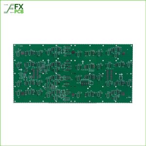
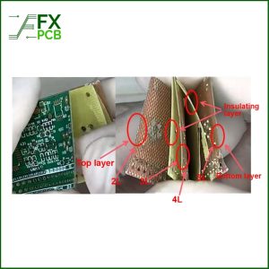
4-layer PCB contains two inner layers and two outer layer circuits, and it is interconnected via electrolytic copper between each layer. Four-layer PCBs are mainly used in electronic devices to offer high signal, low electromagnetic radiation, and strong anti-interference.
Different Stack up for 4-layer PCBs
The most popular stack-up for a 4-layer PCB is SIG-GND-PWR-SIG, where there are signal layers on the top and bottom, and the signals return through adjacent reference planes, which decreases the loop area and the inductance of the signal path. As a result, the signal transmission has lower noise interference, and the radiation is also controlled.
This stack-up is more common on the PCBs with more chips.
Secondly, we can put the signal layers and power plane in the inner layers, and the 4-layer stack up will be GND-SIG(PWR)-SIG(PWR)-GND. The power traces need to be routed with a wider width on signal layers, which can decrease the power current and signal microstrip traces’ impedance. It is one of the most effective configurations for the EMI control perspective.
This kind of stack up is suitable for the components density on the PCB is low, and there will be sufficient space around the ICs
Thirdly, We can also use this stack up PWR-SIG-GND-SIG, but we seldom use this design, as it is not good for the signal stability and Electromagnetic Interference (EMI) Suppression
If you are looking for a PCB supplier to build your 4 Layer PCBs, please contact FX PCB today