Description
What is a copper core PCB?
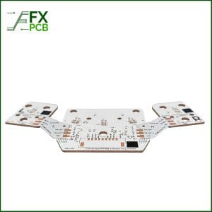
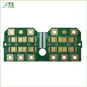
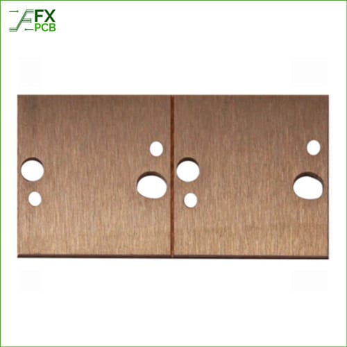
FX PCB manufactures copper core PCBs, also called copper base PCBs, for high-power applications. As a metal core PCB, a copper core PCB uses a copper base to move heat away from high-power devices, and it is widely used in high-power LED lighting, power supplies, automotive electronics and industrial control. A copper core PCB can also be called an MCPCB, a copper-based PCB or a copper PCB.
A copper core PCB is a specialized electronic material for high-power circuits, power converters, LED lighting and other applications. It has excellent heat dissipation and high precision, and it can be produced as a single-sided copper base PCB, a double-sided copper base PCB or a multilayer copper metal core PCB.
Copper base PCB specifications
The table below gives the standard capability for copper base / metal base PCBs from FX PCB.
| Layers | 1–4 |
| Board thickness | 0.5–5.0 mm |
| Max board size | 600 × 1200 mm |
| Copper foil | 1–15 oz |
| Line width / space | 0.10 / 0.075 mm |
| Dielectric thermal conductivity | 1–15 W/m·K |
| Min. dielectric thickness | 38 µm |
| Hole copper thickness | 25–150 µm |
| Min. via hole | 0.1 mm |
| Surface finishes | OSP, ENIG, ENEPIG, immersion tin, lead-free HASL |
| MOQ | 5 pcs |
| Lead time — single-sided copper base | Prototypes: 5 working days; production: 8–10 working days |
| Lead time — double-sided copper base | Prototypes: 8 working days; production: 12–15 working days |
Copper base PCB structure and applications
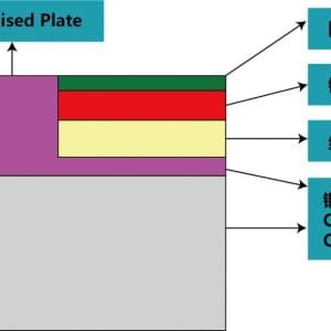
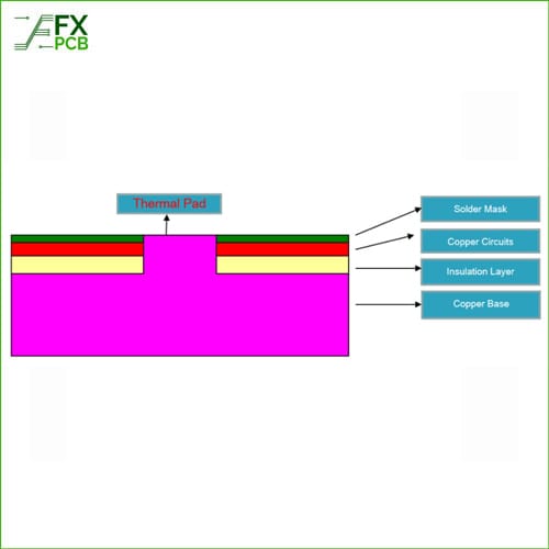
A copper base PCB is built from three main layers: a copper base, a thermal dielectric layer and a circuit layer. The copper base carries heat and gives the board mechanical strength, the thermal dielectric layer insulates the circuit from the base while allowing heat to pass through, and the circuit layer carries the electrical design.
Copper base PCBs are suited to higher power density than aluminum base PCBs. Copper offers better thermal conductivity and greater heat-bearing capacity, so a copper base design can be smaller and more compact for the same high-power duty, with lower warpage and good stability during operation.
Typical applications include:
- High-power LED lighting
- Power supplies and power converters
- Automotive electronics
- Industrial control
- High-power circuits
Thermoelectric separation copper base PCB
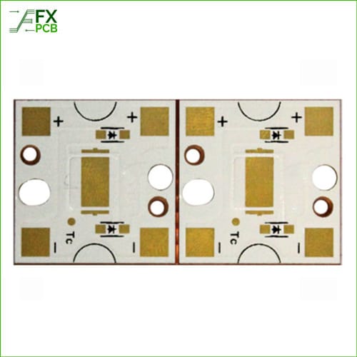
Thermoelectric separation, also called thermal-electric separation, is the flagship copper base PCB process from FX PCB. In this construction, the thermal path and the electrical path are separated: the thermal pad, raised pad or pillar on the copper substrate conducts heat, while the electrodes on the circuit carry the electrical signals. The two parts are isolated by insulation material, so heat and electricity follow different, dedicated paths.
The key difference is the heat path. In a thermoelectric separation copper base PCB, heat travels through solid copper, with a thermal conductivity of 200–400 W/m·K. A dielectric-only design forces heat to pass through the dielectric layer before it can reach the base, while the direct-copper heat path gives high-power LEDs and power devices a much more direct route to the copper base. That is why this construction is well suited to high-power LEDs and high-reliability power devices that must handle thermal stress.
Thermoelectric separation copper base PCB capability: C1100 copper base; board thickness 0.8–5.0 mm; copper foil 1–10 oz; surface finishes OSP, ENIG, ENEPIG and immersion tin.
As with a standard copper core PCB, the raised pad or pillar can be fabricated on the surface, and LED chips can be directly mounted onto the raised pad for ground connection and heat dissipation. This kind of board is also called a sinkpad board or a thermally separated copper substrate.

Embedded copper coin PCB
Where heat is concentrated in one area, an embedded copper coin design can be used instead of a full copper base. A copper coin PCB embeds a copper block, or coin, into an FR4 board at the hot spot, so heat-generating components can be mounted directly onto the copper block and heat can be spread locally. This approach is suited to localized high-current and hot-spot designs where only part of the board needs the strongest thermal path.
Copper core PCB manufacturing process
The copper base PCB production process includes design, copper foil lamination, drilling and plating. Copper foil lamination is the most critical process, as it bonds the copper foil to the substrate, and drilling and plating provide the interlayer connections. A copper core PCB can produce a complex circuit through an etching process, and it can also fabricate the raised pad or pillar on the surface.
How to select a copper core PCB
When selecting a copper base PCB, consider board thickness, copper foil thickness and surface finish together with the thermal requirement. Board thickness ranges from 0.5–5.0 mm for standard copper base PCBs, and from 0.8–5.0 mm for thermoelectric separation boards. Copper foil ranges from 1–15 oz for standard copper base PCBs, and from 1–10 oz for thermoelectric separation boards. For surface finish, OSP, ENIG, ENEPIG, immersion tin and lead-free HASL are available for standard copper base PCBs, while thermoelectric separation boards use OSP, ENIG, ENEPIG and immersion tin.
For assembled boards, FX PCB can support the full build: as a PCBA manufacturer, FX PCB can assemble copper base boards as well as fabricate them.
Frequently asked questions about copper core PCBs
What is the difference between a copper core PCB and a copper base PCB?
There is no difference in the product: the two names describe the same board. A copper core PCB can also be called a copper base PCB, a copper-based PCB, an MCPCB or a copper PCB.
Should I choose a copper core PCB or an aluminum core PCB?
Choose a copper core PCB for higher power density. Copper offers better thermal conductivity and greater heat-bearing capacity than aluminum, so a copper base design can be smaller and more compact for the same high-power duty.
What thermal conductivity options are available?
For standard copper base PCBs, the dielectric thermal conductivity is 1–15 W/m·K. For thermoelectric separation copper base PCBs, the heat path through solid copper has a thermal conductivity of 200–400 W/m·K.
What does thermoelectric separation mean, and what is its benefit?
Thermoelectric separation means the thermal path and the electrical path are separated: the thermal pad, raised pad or pillar conducts heat, while the electrodes carry electrical signals. The benefit is a direct-copper heat path, rather than a dielectric-only path, which suits high-power LEDs and power devices that must handle thermal stress.
What is the maximum board size?
The maximum board size for standard copper base PCBs is 600 × 1200 mm.
What board thickness range is available?
Standard copper base PCBs are available from 0.5–5.0 mm thick. Thermoelectric separation copper base PCBs are available from 0.8–5.0 mm thick.
What copper weight is available?
Standard copper base PCBs use copper foil from 1–15 oz. Thermoelectric separation copper base PCBs use copper foil from 1–10 oz.
What is the minimum order quantity?
The minimum order quantity is 5 pcs.
What is the lead time?
For single-sided copper base PCBs, prototypes take 5 working days and production takes 8–10 working days. For double-sided copper base PCBs, prototypes take 8 working days and production takes 12–15 working days.
What surface finishes are available?
Standard copper base PCBs are available with OSP, ENIG, ENEPIG, immersion tin and lead-free HASL. Thermoelectric separation copper base PCBs are available with OSP, ENIG, ENEPIG and immersion tin.
Request a quote for your copper core PCB
Send your copper core PCB or copper base PCB requirements to FX PCB for a quote. Contact FX PCB to discuss your high-power LED, power supply, automotive electronics or industrial control design, including thermoelectric separation boards and embedded copper coin options.
PROCESS-FLOW: