Rigid-flex PCBs, a combination of rigid and flexible printed circuit boards, offer numerous advantages in electronic design and manufacturing. This article delves into the advantages of rigid-flex PCBs and highlights important considerations, including their design and cost implications.
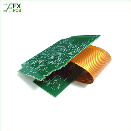
With the development of Flexible PCB (FPC) and rigid PCB, it comes to a new product rigid-flex PCB, which is combined with flex board and Rigid board after the lamination and other technological processes. So it does not only has the characteristics of the flexible circuit boards but also has the characteristics of the rigid circuit boards.
We have several promotional actions, aiming to meet your needs, whether related to urgent deadlines, low cost, or Rigid-flexible prototypes for testing.
Our innovative circuit board technologies are used in the most demanding applications in the automotive sector, in aerospace, in industry and medical technology as well as in telecommunications and computing.
Rigid-flex PCBs provide unparalleled design flexibility, allowing engineers to create complex and compact electronic devices. By combining rigid and flexible sections, designers can optimize space utilization, fit components in tight spaces, and achieve unique form factors. This flexibility enables the development of smaller, lighter, and more durable electronic products.
One key advantage of rigid-flex PCBs is their enhanced reliability and durability. The combination of rigid and flexible substrates reduces the need for connectors and solder joints, minimizing potential points of failure. The absence of interconnecting cables or wires further improves reliability by eliminating the risks associated with loose connections or wire fatigue. Rigid-flex PCBs are also less prone to damage from vibrations, shocks, or bending, making them ideal for applications in harsh environments.
Rigid-flex PCBs offer excellent signal integrity due to reduced signal loss and electromagnetic interference (EMI). The elimination of connectors and shorter signal paths minimize impedance discontinuities, resulting in improved signal transmission. This makes rigid-flex PCBs suitable for high-speed and high-frequency applications where signal integrity is critical, such as aerospace, telecommunications, and medical devices.
Rigid-flex PCBs excel in maximizing space utilization within electronic devices. The combination of rigid and flexible sections allows for three-dimensional routing, enabling designers to route traces and place components in unconventional ways. This spatial efficiency is especially valuable in miniaturized or compact devices where every millimeter counts. By efficiently utilizing space, rigid-flex PCBs enable the integration of more features and functionality into smaller form factors, unlocking new possibilities for electronic design.
Designing rigid-flex PCBs requires careful consideration of layer stacking and flex area placement. The arrangement of rigid and flexible sections should be optimized to ensure mechanical integrity and prevent stress concentration. Additionally, proper placement of components, traces, and vias in the flexible areas is crucial to prevent fatigue or damage during flexing.
Efficient thermal management is vital in rigid-flex PCB design to ensure the reliability and performance of electronic devices. Thermal dissipation can be challenging due to the combination of rigid and flexible materials. Engineers must consider heat-generating components, thermal vias, and proper airflow to prevent overheating and ensure optimal operation of the device.
Testing and verification processes for rigid-flex PCBs differ from traditional rigid PCBs due to their flexible sections. Specialized testing techniques, such as flex testing, must be employed to validate the integrity and functionality of the flexible portions. Rigorous testing and verification are essential to ensure the reliability and longevity of the finished product.
When designing rigid-flex PCBs, it is crucial to consider the flexibility and bending radius of the flexible sections. The choice of materials and their thickness directly impacts the ability of the PCB to bend without causing stress or damage. Engineers must carefully select materials with suitable flexibility and ensure that the bending radius is within acceptable limits. Proper consideration of these factors ensures that the rigid-flex PCB can withstand the intended bending and flexing operations without compromising its structural integrity or functionality.
Transition zones, where the rigid and flexible sections of the PCB connect, require special attention to maintain signal and power integrity. These areas often experience higher stress due to repeated flexing and bending. To ensure reliable performance, designers must carefully route signal traces, power planes, and ground connections in these transition zones. Minimizing impedance variations and avoiding sharp transitions are crucial for maintaining signal integrity and preventing potential signal degradation or EMI issues.
Rigid-flex PCBs often involve a higher initial investment compared to traditional rigid PCBs. The specialized manufacturing processes, unique materials, and additional design considerations contribute to the higher upfront costs. However, it’s important to weigh this against the overall benefits and long-term savings in terms of reduced assembly and maintenance costs.
Despite the higher initial costs, rigid-flex PCBs can lead to improved assembly and integration efficiencies. The elimination of connectors and cables simplifies the assembly process, reduces labor requirements, and lowers the risk of assembly errors. These factors contribute to overall cost savings during the manufacturing phase.
Rigid-flex PCBs offer potential long-term cost savings due to their enhanced reliability and durability. The reduced risk of failure, maintenance, and repair costs can outweigh the initial investment. Moreover, the compact form factor and lightweight nature of rigid-flex PCBs can lead to cost savings in transportation and packaging.
When considering the cost of rigid-flex PCBs, volume production and the economy of scale play a significant role. As the production quantity increases, the per-unit cost of manufacturing rigid-flex PCBs decreases. This is due to optimized production processes, efficient material utilization, and reduced setup and tooling costs. Therefore, for large-scale production runs, the cost per unit of rigid-flex PCBs becomes more competitive and economically viable.
Design iterations and prototyping are essential stages in the development of any electronic product. Rigid-flex PCBs, while offering design flexibility, may involve additional costs during the prototyping phase. Iterative design changes, modifications to accommodate specific requirements, and prototyping of complex form factors can impact the overall cost. It’s crucial to factor in these costs during the initial budgeting and planning stages to ensure a smooth and cost-effective product development process.
Rigid-flex PCBs offer significant advantages in terms of design flexibility, reliability, and signal integrity. However, their design requires careful consideration of layer stacking, thermal management, and testing processes. While they may involve a higher initial investment, the long-term benefits and potential cost savings make rigid-flex PCBs a compelling choice for various applications in the electronics industry.

I am Peter Gong. I have been working in PCB and PCBA industry for 15+ years now. I have been a part of the PCB revolution with my dedication to circuit board technologies and creative ideas. I write in FX PCB to impart my knowledge on PCB and PCBA for all circuit board lovers, manufacturers, and users.
WhatsApp us