

Description
- Communications
- Industrial
- Consumer Electronics
- Aerospace
- Automotive
- Medical
- Transportation
Rigid-Flex PCB Capability:
| Items | Mass Production | Low Volume | |
| Total Layers | 2~16L | 20L | |
| Layers of sofe | 10L | 16L | |
| PCB Thickness | ≤2.4mm | / | |
| Line width/Line space | Inner layer | 3mil/3mil (HOz) | 2.5mil/2.5mil (HOz) |
| Outer layer | 4mil/4mil (1Oz) | 3mil/3mil (1Oz) | |
| Hole Ring | ≥6mil | 4mil | |
| Impedance Control | +/-10% | / | |
| Drilling | Machine drilling | ≥8mil | 6mil |
| Laser drilling | 5mil/6mil | 4mil | |
| Aspect Ratio | 10:01 | 16:01 | |
| Surface Coating | ENIG, Immersion Silver, Immersion Tin, OSP | ||
Rigid-flex Attributes:
| Material | Fr4+PI |
| Layers | 6L buried holes 2-4Layer |
| Copper thickness | 1oz |
| Board thickness | 1mm |
| Surface treatment | HAL Leadfree |
| Track width/Space | 5/5mil |
| Hole size | 0.3mm |
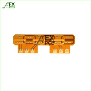
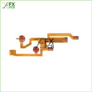
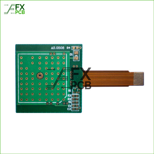
What is a Rigid-Flex PCB?
Rigid flex printed circuit boards are boards using a combination of flexible and rigid board technologies in an application.
Most rigid flex boards consist of multiple layers of flexible circuit substrates attached to one or more rigid boards externally and/or internally, depending upon the design of the application.
Benefits of Rigid-Flex PCBs
• Space requirements can be minimized by applying 3D
• By removing the need for connectors and cables between the individual rigid parts, the board size and overall system weight can be reduced.
• By maximizing space, there is often a lower count in parts.
• Fewer solder joints assure higher connection reliability.
• Handling during assembly is easier in comparison with flexible boards.
• Simplified PCB assembly processes.
• Integrated ZIF contacts provide simple modular interfaces to the system environment.
• Test conditions are simplified. A complete test before installation becomes possible.
• Logistical and assembly costs are significantly reduced with Rigid-Flex boards.
• It is possible to increase the complexity of mechanical designs, which also improves the degree of freedom for optimized housing solutions.