How to Use a Breadboard and How It Works

Breadboards are indispensable tools in the world of electronics and prototyping, serving as the foundation for creating and testing various electronic circuits. They are especially popular among beginners and experienced hobbyists due to their ease of use and versatility. In this comprehensive guide, we will explore the ins and outs of using a breadboard and delve deep into how it works, equipping you with the knowledge needed to become a proficient electronics enthusiast.

Table of Contents

Our Recommended Quick Turn PCB

Fast Turnaround PCBA

As a fast turnaround or quick-turn PCB Assembly Manufacturer /factory in Shenzhen China, FX PCB is able to fulfill orders in a fast delivery time with our modern technologies used in production.

Our factory carries out the assembly and installation of printed circuit boards to order. During the development and manufacturing process, constant quality control is carried out. We strictly follow your Gerber file and Bom list for your fast turnaround or quick turn PCBA projects, and we will also be glad to suggest you the alternative for your passive components to decrease your cost, but all replacement components need you to approve and make the final decision on whether you want to use them.


Understanding the Breadboard

Before we dive into the practical aspects of using a breadboard, let’s thoroughly understand its structure and components.

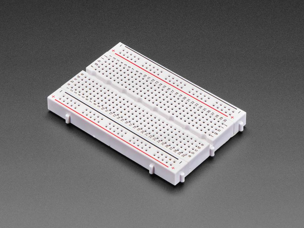
A breadboard typically consists of a rectangular plastic board with numerous holes arranged in rows and columns. These holes serve as insertion points for electronic components and facilitate connections without the need for soldering. There are two main sections on a breadboard: the terminal strips and the bus strips.

Terminal Strips:

  • The horizontal rows of holes on a breadboard are called terminal strips.
  • Each row typically contains five holes, conveniently labeled with numbers (usually ranging from 1 to 30 or more) for easy reference.
  • The five holes in each row are electrically connected, providing a common connection point for components.

Bus Strips:

  • The two vertical columns on the sides of the breadboard are known as bus strips.
  • These bus strips run the entire length of the board and are usually labeled as + (positive) and – (negative).
  • The + and – bus strips are used to provide power to the breadboard.

How Does a Breadboard Works

With a solid understanding of the breadboard’s structure, let’s delve deeper into how it works.

Component Placement:

  • Electronic components, such as resistors, LEDs, capacitors, transistors, and integrated circuits, are inserted into the holes on the breadboard.
  • Components can be placed both horizontally and vertically across the terminal strips.
  • Ensure that the component’s legs or leads are securely inserted into the appropriate holes.

Electrical Connections:

  • The fundamental principle of a breadboard is the electrical connections it offers.
  • The holes in each row of the terminal strips are electrically connected, enabling components to share a common electrical connection.
  • Components can be connected in parallel by placing them in the same row or in series by placing them in different rows.
  • The ability to make both series and parallel connections provides tremendous flexibility in circuit design.

Power Distribution:

  • The + and – bus strips on the sides of the breadboard are used to supply power to your circuit.
  • Typically, the + strip is used for the positive supply voltage (e.g., 5V or 3.3V), while the – strip is used for the ground (0V).
  • You can connect power sources, such as batteries, benchtop power supplies, or external power adapters, to these bus strips.
  • Power rails are used to distribute power from these bus strips to different sections of the breadboard, making it easy to power various parts of your circuit.

Jumper Wires and Interconnections:

  • Jumper wires are essential accessories when working with a breadboard.
  • They are used to create connections between different points on the breadboard.
  • Jumper wires can be used to connect components, bridge gaps, and route signals.
  • They come in various lengths and colors, allowing for customization of your circuit layout.

Testing and Prototyping:

  • Breadboards excel in the prototyping of electronic circuits because they enable you to rapidly assemble and modify circuits without the need for soldering.
  • You can quickly test your circuit’s functionality, make adjustments, and troubleshoot issues as needed.
  • The ability to experiment with various components and configurations is a significant advantage for both beginners and experienced electronics enthusiasts.
Breadboard

How to Use a Breadboard?

Now that we’ve covered the basics of breadboarding, let’s explore some advanced techniques to take your breadboarding skills to the next level.

Using Breadboard Power Supplies:

  • While you can use external power sources, breadboards often come equipped with built-in power supplies.
  • These built-in power supplies allow you to easily provide voltage to your circuit without additional connections.
  • Understanding how to use these built-in power supplies can simplify your breadboarding experience.

Breadboard Layout and Organization:

  • As your circuits become more complex, organization and layout become critical.
  • Learning how to arrange components effectively and minimize clutter on the breadboard can help you build more reliable and maintainable circuits.
  • Consider using color-coding or labeling for better organization.

Signal Integrity and Noise Management:

  • In advanced electronics projects, signal integrity and noise management become significant concerns.
  • Techniques such as using decoupling capacitors, minimizing signal crosstalk, and carefully routing sensitive signals can enhance the performance of your circuits.

Breadboard-Compatible Components:

  • Some components are designed specifically for breadboarding, making them easier to work with.
  • Breadboard-compatible components often have leads or pins that fit neatly into the breadboard holes without bending or requiring special adapters.

Common Mistakes and Troubleshooting

As with any skill, there are common mistakes that beginners might encounter when working with breadboards. Understanding these issues and how to troubleshoot them is essential.

Loose Connections:

  • Components that are not securely inserted into the breadboard holes can result in loose connections.
  • To troubleshoot, ensure that all components are firmly seated in their respective holes.

Short Circuits:

  • Accidental short circuits can occur if two adjacent rows on the breadboard are bridged with a jumper wire or component.
  • Carefully inspect your connections and remove any unintended bridges to resolve short circuits.

Incorrect Component Orientation:

  • Some components, like diodes and polarized capacitors, have a specific orientation.
  • Placing these components incorrectly can lead to circuit malfunctions.
  • Always double-check the component datasheet or markings to ensure the correct orientation.

Faulty Components:

  • Sometimes, components themselves may be faulty.
  • To identify faulty components, you can swap them with known working ones or use a multimeter for testing.

Conclusion

In conclusion, a breadboard is an indispensable tool for anyone working with electronics. By mastering the art of breadboarding, you can swiftly prototype and experiment with a wide range of electronic circuits. 

Whether you’re a beginner taking your first steps into electronics or an experienced enthusiast tackling advanced projects, a solid understanding of how to use a breadboard and how it works is a valuable asset. So, pick up a breadboard, gather your components, and embark on your journey to creating innovative electronic projects with confidence and skill.

Picture of Peter Gong
Peter Gong

I am Peter Gong. I have been working in PCB and PCBA industry for 15+ years now. I have been a part of the PCB revolution with my dedication to circuit board technologies and creative ideas. I write in FX PCB to impart my knowledge on PCB and PCBA for all circuit board lovers, manufacturers, and users.