Welcome to a comprehensive guide on understanding PCB motor and their role in circuit design. In this article, we will delve into the fundamentals of PCB motor, discuss the circuit design considerations required to drive them and explore the crucial role played by the motor stator. Whether you are an electronics enthusiast, a DIY robotics enthusiast, or a professional engineer, this article will equip you with valuable insights into PCB motors. So, let’s get started!

FX PCB can provide the ALN(Aluminum oxide) and AIO203(Aluminum Nitride) Ceramic PCB, we can make ENEPIG, ENIG, Immerison silver surface,you can check the material datesheet and our capability from the below tables.
The ceramic circuit board has the following characteristics: high-temperature resistance, high electrical insulation, low dielectric constant, low dielectric loss, high thermal conductivity, good chemical stability, and the thermal expansion is almost can be coefficients of components.
Ceramic PCB is actually made of electronic ceramic materials and can be made into various shapes. We are best Ceramic PCB Manufacturer in China
Conformal coating is a thin layer of protective material that conforms to the contours of a PCB, forming a barrier against external factors. Among the various options available, silicone conformal coating stands out as a popular choice due to its excellent properties such as high flexibility, temperature resistance, and chemical resistance.
PCB motors have revolutionized the field of motor technology by providing compact and efficient solutions for motion control. Their miniature size, low power consumption, and precise control capabilities make them ideal for limited space applications, energy efficiency is crucial, and accurate motion control is required. From drone stabilization systems to autofocus mechanisms in cameras, PCB motors have found their way into countless innovative products.
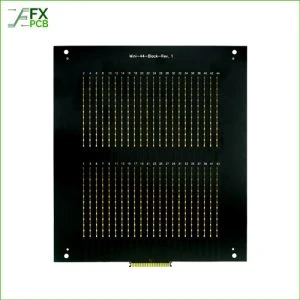
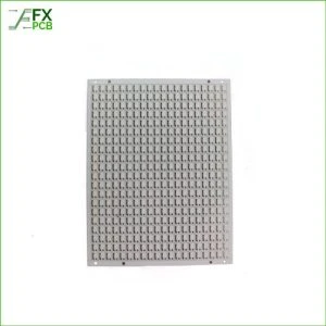
As mentioned, PCB motors are motors where the rotor and stator are integrated into a printed circuit board. The printed circuit board serves as the motor components’ mechanical structure, electrical connection, and housing. PCB motor operate on the principle of electromagnetic induction, where the interaction between the rotor and stator magnetic fields generates rotational motion.
There are two primary types of PCB motors: brushed and brushless. Brushed PCB motors use brushes and a commutator to control current flow to the rotor windings, while brushless PCB motors rely on electronic commutation to achieve the same result. Brushless PCB motors offer several advantages over brushed motors, including higher efficiency, longer lifespan, and reduced electromagnetic interference.
PCB motors offer a range of advantages that make them highly desirable for various applications:
PCB motor is highly efficient, converting a high percentage of electrical input power into mechanical output power. Additionally, their compact design allows for integration into space-constrained systems.
PCB motor offer precise control over speed, position, and torque, making them suitable for applications that require accurate motion control. Furthermore, their solid-state construction enhances their reliability and reduces the need for maintenance.
PCB motor is designed to be energy-efficient, consuming minimal power while providing the desired level of performance. This characteristic is particularly important in battery-powered devices, where power conservation is crucial.
PCB motors can be easily customized to meet specific application requirements. The design flexibility offered by PCBA technology allows for incorporating additional features, such as sensors and feedback mechanisms, without significantly increasing the motor’s size.
With these advantages in mind, it’s clear why PCB motors have gained immense popularity across various industries.

When designing a circuit for driving PCB motors, careful consideration must be given to the power supply requirements. The voltage and current rating of the power supply must match the motor’s specifications to ensure proper operation. Voltage regulation techniques such as voltage or switching regulators may be employed to maintain a stable power supply voltage, especially in battery-powered applications where the input voltage can vary.
Motor driver circuits are essential components in PCB motor control systems. These circuits provide the necessary power and control signals to drive the motor.
One standard motor driver configuration is the H-bridge, which allows for bidirectional control of the motor’s rotation. Pulse Width Modulation (PWM) techniques are often employed to control the motor’s speed by varying the duty cycle of the PWM signal. Current limiting and protection mechanisms are also integrated into motor driver circuits to prevent damage to the motor and control the current flow.
Various control signals and feedback mechanisms are utilized to achieve precise control over the PCB motor. The most common control signal is the Pulse and Direction (P&D) signal, where the pulse signal determines the motor’s step or rotation, and the direction signal controls the motor’s rotational direction.
Additionally, encoders can provide position feedback, enabling closed-loop control of the motor. Sensorless control techniques, which rely on motor current and voltage measurements, are also utilized in specific applications.
The motor stator plays a vital role in the operation of PCB motors. The stationary part of the motor houses the stator windings, which generate the magnetic field necessary for motor rotation. The stator is typically composed of laminated magnetic cores and copper windings.
The design of the motor stator significantly impacts the motor’s performance. Factors such as the selection of core materials, coil winding techniques, and the shape of the stator windings influence the motor’s efficiency, torque output, and overall performance. Optimal stator design ensures minimal energy loss and maximum magnetic field generation.
While motor stators are generally reliable, faults can occur over time due to various factors, including electrical stress, overheating, and mechanical wear. Common stator faults include insulation breakdown, winding shorts, and open circuits. Diagnostic techniques such as insulation resistance measurements and thermal imaging can be used to identify stator faults. Regular maintenance practices such as cleaning, lubrication, and temperature monitoring can help prolong the stator’s lifespan and ensure optimal performance.
In conclusion, understanding PCB motors and the role of the motor stator is essential for anyone working with motion control systems. PCB motors offer compactness, efficiency, precision, and customizability, making them popular in various applications. The circuit design considerations discussed in this article, including power supply requirements, motor driver circuitry, and control signals, are crucial for driving PCB motors effectively. Additionally, the motor stator’s design and maintenance are vital in achieving optimal motor performance and longevity.
As technology advances, we expect further developments in PCB motor technology, including improved efficiency, higher power densities, and advanced control techniques. By staying informed and embracing these advancements, engineers and enthusiasts can harness the full potential of PCB motors and push the boundaries of innovation.
Can I use a PCB motor in my DIY robotics project?
Absolutely! PCB motors are widely used in DIY robotics projects due to their compact size, efficiency, and precise control capabilities. They can provide the necessary motion control for your project while conserving space and power.
Are PCB motors suitable for high-speed applications?
Yes, PCB motors can be ideal for high-speed applications, especially brushless PCB motors. With the right design and control techniques, PCB motors can achieve high rotational speeds while maintaining accuracy and reliability.
How do PCB motors compare to traditional motors in terms of cost?
PCB motors can be cost-effective compared to conventional motors, especially considering their compactness and integrated design. However, the price depends on the motor type, power requirements, and customization needs.
What are the typical lifespan and reliability of PCB motors?
PCB motors are designed for long-term reliability. PCB motors can have lifespans comparable to traditional motors with proper maintenance and operation within specified parameters. It’s important to follow recommended maintenance practices and avoid operating the motor beyond its rated limits.

I am Peter Gong. I have been working in PCB and PCBA industry for 15+ years now. I have been a part of the PCB revolution with my dedication to circuit board technologies and creative ideas. I write in FX PCB to impart my knowledge on PCB and PCBA for all circuit board lovers, manufacturers, and users.
WhatsApp us