PCB or Printed Circuit Board is the base of any electrical device. The board is itself self-contained and has a heat-dissipating substrate. It dissipates the heat from the inter-connected electric components that sit on the circuit board.
Depending on the construction procedure, there are many types of printed circuit boards in the market. It depends on the number of layers the printed circuit board has, its flexibility, and rigidity. Thus, there’re mainly six types of PCB in the electric and electrical industry.
Each of these printed circuit boards comes with its unique benefits. Its design and advantages will allow you to know where to use the PCB.
So, you must know the different kinds of printed circuit boards and their benefits for better improvement of your device. And we will do the same today.
Here, we present the six common printed circuit board types and their usage advantage.
A PCB holds various components in its holes. These holes are connected using the copper track and each PCB type has a specific design. Its design will determine where and how can you use the printed circuit board.
The printed circuit board is designed in layers. It can be single, dual, or multiple layers. These have, thus, three classifications of printed circuit boards.
As the name suggests the single-sided printed circuit board is made with one layer of the substrate. Thus, it equips with one layer of the metal base.
One end or side of this printed circuit board has a thin metal coating. The coating is often made of copper because of its excellent electrical conductivity. On the top of this copper layer, you will see a protective solder mask.
Finally, it has a silkscreen coating which is on the top layer. It marks the different elements on the PCB. It accommodates various electronic components on its single layer.
You will see its application on easy electronic components mostly. Also, it has a pretty simple design and construction idea. So, beginners will kick off their PCB manufacturing with this single-layer PCB. It is the cheapest of all printed circuit boards and produced in mass for its cheaper price.
You will see its usage in electronic toys, relays, and power sensors.
Benefits:
Unlike the single-layer PCB, the double-sided PCB has metal conductive layers on each substrate. That’s why it got the name dual-layer printed circuit board. Also, electrical components are attachable on both sides of the substrate. It enables the double-sided PCB to be used in complex electronic devices.
So, it is no wonder that the dual-layer PCB is more popular and familiar than the single-sided PCB. Its holes will allow the manufacturer to set and attach the electronic components from one side to another with a good heat dissipation facility.
It uses mainly two mounting techniques to connect the components on either side of the PCB. These mounting techniques are-
Thesedays, modern manufacturers prefer SMT because it allows you to mount several components in a smaller place. So it saves space. You will see its use in many modern-day electronica and electric devices. It includes smartphones, amplifies, test equipment, etc.
Benefits:
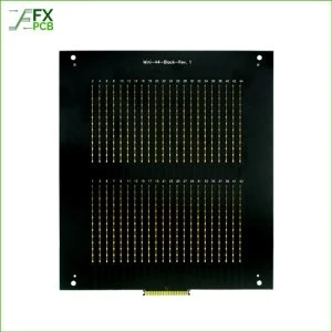
The PCB with multiple layers means it has more than two copper layers on the substrate. Since the number of layers increases, the PCB complexity and capacity also improves massively. So, it is usable in complex devices which need a densely printed circuit board with more elements and a smoother heat dissipation facility.
The extra layer of this PCB is added beyond the other two substrate sides on the top and bottom end. Its thicker configuration will allow the manufacturer to develop compound designs with PCBA for use in different devices.
The additional layer works as the power planes in this type of printed circuit board. On one end it supplies the power to the circuit and on the other end, it reduces electromagnetic interface. There will be many signal levels at the middle of this power plane or extra layer. It decreases the growing EMI (electromagnetic interface) level and allows the device to work with enhanced efficiency.
Benefits:
Enhanced space for power supply and conductivity.
Printed circuit boards can be rigid or flexible. Also, some manufacturers produce rigid-flex PCBs which have both flexibility and rigidity for versatile use. The classifications include-
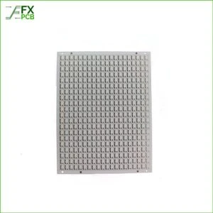
Rigid printed circuit board comes with a solid base fabricated from solid metals. Since it is made from solid materials, you can’t bend it. Thus, there’s less chance of the circuit board twisting and breaking down in the middle of your device manufacturing.
The most common material used for the substrate of rigid PCB is fiberglass. The fiberglass has a high amount of solidity while still is on the lighter side. Some users will also refer to it as the inflexible printed circuit board.
The best example of these boards the motherboard used in your computer or laptops. The components on the board are marked clearly. So, you know which component is where and it makes the board maintenance easy.
Benefits:
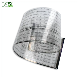
This kind of printed circuit board is just the opposite of what you read in the rigid PCB section. The substrate material used in flexible PC is not solid rather a bit flexible. The PCB is available in different layers that we described in the previous sections. So, you are at liberty to choose from the single, double or multi-layer flexible PCBs.
Also, such availability will relieve you from the electrical component assembly on the flexible base. You will see its use in satellites, because of its ability to restore massive wiring. It also saves massive space due to compact engineering.
Benefits:
This printed circuit board type blends the benefit of both flexible and rigid PCBs with great construction techniques. It is often a multi-layer printed circuit board. The primary design is a rigid PCB which is then attached with the flexible PCB.
Benefits:
Here we described the six main types of printed circuit boards. But the classification is not limited here. Some people will classify the PCBs according to the material used for its substrate which includes copper, aluminum, fiberglass, and ceramic.
Another two important types include aluminum-backed and high-frequency PCBs. Aluminum-backed PCBs with their superior heat dissipation capacity are used in power supplies and LEDs. The high-frequency PCBs, on the contrary, are used in microchips and communication devices. You can easily get all these printed circuit boards from FX PCB. We deliver these prototype PCBs both in bulk and a small amount to meet your project needs.

I am Peter Gong. I have been working in PCB and PCBA industry for 15+ years now. I have been a part of the PCB revolution with my dedication to circuit board technologies and creative ideas. I write in FX PCB to impart my knowledge on PCB and PCBA for all circuit board lovers, manufacturers, and users.
WhatsApp us