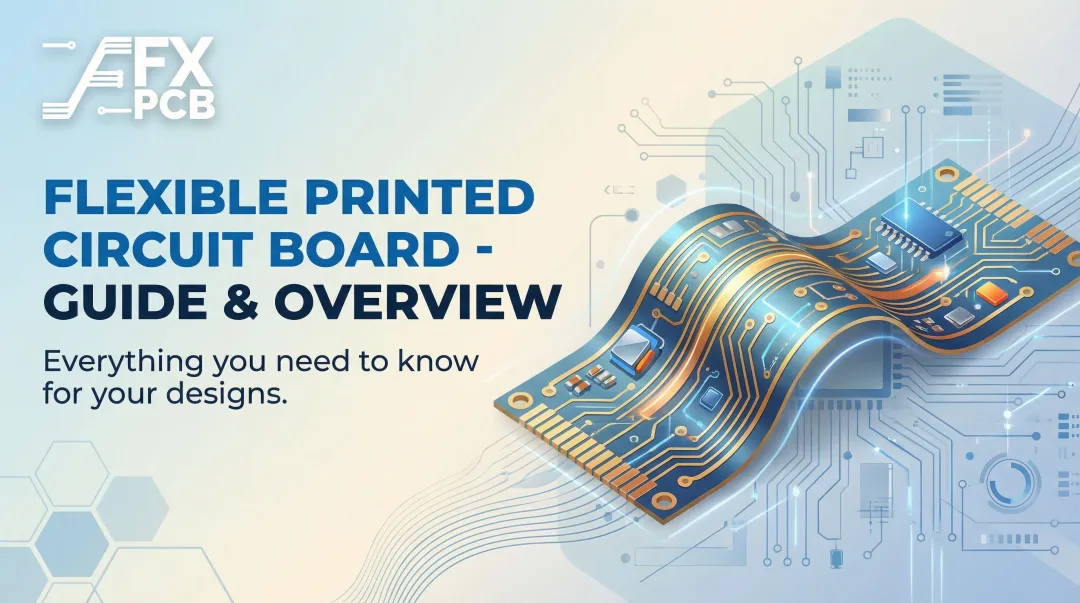

Flexible PCBs (FPCs) have moved from specialty component to mainstream engineering decision, and the global FPCB market reflects this shift — valued at $23.89 billion in 2024 and projected to reach $50.90 billion by 2030 at a 13.7% CAGR. But market growth alone doesn't tell engineers what they actually need to know: where do flexible PCBs deliver measurable advantages, and where do those advantages disappear if the design process ignores flex-specific constraints?
This article addresses both questions directly.
Key Takeaways
- Flexible PCBs are thin, bendable circuits built on polyimide or polyester substrates that replace rigid boards and wiring harnesses in space- or weight-constrained assemblies
- Flex circuits can cut harness weight by 60–80% and volume by 70–90% versus traditional wire-bundle harnesses in automotive applications
- Core advantages: space and weight savings, vibration resistance, 3D design freedom, and lower assembly costs from fewer interconnects
- Flex PCBs deliver the most value in dynamic flex, harsh environments, miniaturization, or high-volume assembly — they complement rigid boards, not replace them
- DFM review before production is non-negotiable; skipping it is the fastest way to lose all these advantages
What Are Flexible PCBs?
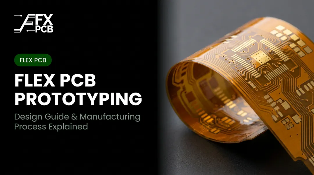
A flexible PCB is a circuit board built on a thin, flexible substrate — typically polyimide (PI) or polyester (PET) — that allows the board to bend, fold, or conform to a three-dimensional shape without breaking electrical continuity.
Kapton polyimide film is the dominant substrate for high-reliability flex applications. It's available in nominal thicknesses from 7.5 to 125 microns and performs across a temperature range of -269°C to 400°C, making it the default choice for medical, aerospace, and automotive applications where thermal extremes and mechanical stress are constants.
Where FPCs Replace Conventional Assemblies
- Automotive dashboards and instrument clusters, replacing wire-bundle harnesses
- Medical implantables and hearing aids requiring miniaturized packaging
- Printers, robotics, and camera assemblies connecting moving parts
- Smartphones and wearables where every cubic millimeter matters
Flexible PCBs deliver specific, measurable outcomes: thinner profiles, lighter assemblies, fewer connection points, and greater mechanical resilience in tight spaces where rigid alternatives simply don't fit.
SFX PCB manufactures single-sided, double-sided, and multilayer flex configurations, as well as rigid-flex combinations, with flex layer counts up to 8 layers for production runs and up to 12 flexible layers within rigid-flex boards for specialized applications.
Key Advantages of Flexible PCBs in Electronic Applications
The advantages below are framed around operational impact — the kind that shows up in product weight specifications, field failure rates, assembly efficiency, and total cost of ownership.
Advantage 1: Significant Space and Weight Reduction
Flexible PCBs built on substrate films as thin as 12–125 microns eliminate the physical bulk of rigid boards, wiring harnesses, connectors, and ribbon cables. The resulting assembly conforms to the available space in the device rather than dictating that space around it.
Traces are etched directly onto the flex substrate, layers are bonded using adhesive film, and the assembly compresses what was once a multi-component system into a single contoured circuit. Enclosures shrink without sacrificing circuit density.
The numbers in context:
- FPCBs can save up to 60% of space and weight compared with rigid PCBs
- In automotive flex harness applications, CelLink circuits reduced wire-harness weight by 60–80% and volume by 70–90% versus traditional wire-bundle harnesses, validated by BMW i Ventures in 2019
- Lear, a Tier-1 automotive supplier, confirmed CelLink products reduce wire-harness weight by more than 70% and volume by more than 90% versus existing wiring technologies

These aren't abstract design benefits. In EV applications, Lear explicitly links lower wiring weight to increased vehicle range. The U.S. Department of Energy has documented that a 10% reduction in vehicle weight can yield 6–8% fuel economy improvement — context that frames why automotive OEMs are investing heavily in flex harness technology to replace assemblies that can contain more than 2,000 individual wires.
Where this matters most:
- Wearables and medical implantables where size is a physiological constraint
- EV platforms where wiring harness weight reduction directly affects range
- Aerospace and drone applications where payload efficiency is critical
KPIs impacted: Product weight saved per unit, board footprint area, component and interconnect count, enclosure volume
Advantage 2: Reliability and Durability in Harsh Environments
Conventional assemblies fail at predictable points: hand-crimped connectors, soldered wire joints, and multi-board interconnects all degrade under vibration, thermal cycling, and mechanical stress. Flexible PCBs eliminate these failure modes by design.
The flex substrate absorbs and distributes mechanical stress across its surface rather than concentrating it at solder joints. Fewer bulky connectors means fewer components that can loosen, corrode, or fail.
Why This Matters Beyond the Engineering Case
In medical device applications, reliability isn't just an operational metric — it's a patient safety and regulatory requirement. Reducing failure points supports compliance with IPC-A-610 Class 3 acceptability standards for life-critical assemblies, where the consequences of a connection failure are unacceptable. SFX PCB holds ISO13485 certification and adheres to IPC-A-610 Class 2/3 standards, directly relevant for customers manufacturing medical and aerospace-grade assemblies.
The design principle is straightforward: CelLink's flex harness architecture allows direct soldering to controller PCBs and zone-based routing without increasing terminal and connector content, removing entire categories of potential failure from the assembly.
Where this matters most:
- Automotive underhood electronics under constant vibration and thermal cycling
- Medical implantables and diagnostic equipment where failure is not an option
- Aerospace and satellite systems where post-deployment servicing is impossible
- Industrial automation where unplanned downtime carries direct cost consequences
KPIs impacted: Field failure rate, warranty claim frequency, rework costs, compliance audit outcomes
Advantage 3: Design Freedom and Complex 3D Form Factor Capability
Rigid PCBs exist in a flat plane. That constraint shapes everything: enclosure geometry, connector placement, cable routing, and ultimately product size. Flexible PCBs remove that constraint entirely.
A single flex PCB can replace multiple rigid boards linked by connectors, route around structural components inside a device, and interface with multiple connectors at different positions in three-dimensional space, all while maintaining conductor density comparable to rigid alternatives.
The Space Application Case
Polyimide's performance in vacuum environments deserves specific mention. NASA's outgassing database documents Kapton H/HN with a Total Mass Loss (TML) of 1.3%, Recovered Mass Loss (RML) of 0.2%, and a Collected Volatile Condensable Material (CVCM) value of 0.02% — values that meet the threshold requirements for spaceflight material qualification. This makes polyimide flex the substrate of choice for satellite routing and space hardware, where ribbon cable insulation materials with higher outgassing values would contaminate sensitive optical and sensor systems.
On the design process side, consolidating a multi-board, multi-connector sub-system into a single flex assembly reduces interconnect decisions, eliminates cable routing problems, and accelerates prototype validation. CelLink's circuits can integrate busing, fusing, and monitoring functions into a single circuit, demonstrating what this consolidation looks like at production scale.
Most relevant for:
- Heads-up displays and helmet-mounted avionics systems
- Cochlear implants, hearing aids, and endoscopic medical devices
- Foldable and curved consumer electronics
- Satellite and spacecraft hardware where outgassing behavior is a qualification criterion
What to measure: Number of connectors per assembly, design iteration cycles, prototype-to-validation lead time, internal clearance utilization
Advantage 4: Assembly Cost Reduction and Manufacturing Efficiency
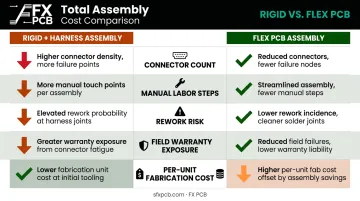
Flexible PCBs carry a higher per-unit fabrication cost than basic rigid boards. That comparison misses the point. The relevant metric is total assembly cost — including connectors, cables, labor, rework, and field warranty — not bare board cost alone.
The labor context for conventional harness assembly is significant. One estimate puts labor at approximately 30% of harness assembly cost (Assembly Magazine, 2021), while another analysis suggests manual labor can account for up to 95% of automotive wire-harness production cost (Connector Supplier). Either figure illustrates why automating this step through flex circuit production represents a meaningful cost lever.
CelLink's flex harness production uses automated equipment and a tool-less process that shortens wiring supply chains, directly addressing the labor intensity that makes manual harness assembly expensive to scale and difficult to quality-control. Direct soldering to controller PCBs eliminates categories of mechanical fasteners and ancillary assembly materials entirely.
The correct cost comparison:
| Cost Factor | Rigid + Harness Assembly | Flex PCB Assembly |
|---|---|---|
| Connector count | High | Reduced or eliminated |
| Manual labor steps | High (hand-routing, crimping) | Reduced via automation |
| Rework risk | High (manual variation) | Lower (automated process) |
| Field warranty exposure | Higher (connector failure points) | Lower (fewer failure points) |
| Per-unit fabrication cost | Lower | Higher |
Best suited for:
- High-volume consumer electronics where per-unit savings compound at scale
- Automotive wiring assemblies where harness labor costs are substantial
- Medical device production where rework carries regulatory implications
Key metrics: Total assembly cost per unit, defect rate, rework hours, BOM complexity, connector and cable component count
What Happens When Flexible PCBs Are Avoided or Misapplied
The cost of defaulting to rigid boards in applications that need flex shows up predictably: enclosures that fail size requirements at design review, wiring harnesses that generate field reliability failures at connectors, and manual assembly processes that introduce defect variability at scale.
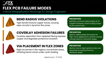
The misapplication risk runs in both directions. Specifying flex without accounting for flex-specific constraints produces its own failure modes:
- Bend radius violations — copper fracture, open circuits, or delamination
- Coverlay adhesion failures — protective layer separation under mechanical stress
- Via placement in flex zones — stress concentration at through-hole locations during flexing
These failures produce rework costs, delayed launches, and the incorrect conclusion that flex circuits are inherently unreliable. Flex circuits are reliable by design; the failures trace back to ignored design rules, not the technology itself.
Those design-rule failures also obscure a separate cost problem. Rigid-and-harness assemblies tend to appear cheaper at prototype stage while generating higher-than-expected costs in warranty claims, field service, and redesign cycles. A well-designed flex PCB typically delivers lower total cost of ownership across the full production run.
How to Get the Most Value from Flexible PCBs
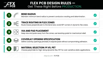
The advantages of flexible PCBs are only fully realized when the design process accounts for flex-specific constraints from the start. Key areas include:
- Bend radius — calculated based on layer count and whether the application is static or dynamic flex
- Trace routing in flex zones — straight traces perpendicular to the bend axis reduce stress concentration
- Via and pad placement — components and through-holes placed away from active bend regions
- Coverlay opening specification — matched to the manufacturer's process capabilities, not approximated
- Material selection — polyimide for high-temperature and high-reliability applications; polyester (PET) for lower-temperature, cost-sensitive applications
IPC-2223E is the governing design standard for flexible and rigid-flexible printed boards. It covers bend areas, conductor design, material selection, and stiffener placement — the right reference for engineering decisions on flex-specific design rules.
DFM review is the most critical step before committing a design to production. A thorough DFM check validates bend radii, traces in flex zones, pad placement relative to bend areas, and material specifications — catching errors that otherwise surface as field failures or rejected builds.
SFX PCB provides free DFM analysis on every order, including prototype quantities. Submissions receive a response within 12 hours and an official quotation within 24 hours.
Flex PCB selection should be a design-phase decision, not a late-stage component swap. The highest-value outcomes come when flexibility requirements, mechanical constraints, and thermal environment are factored into the initial layout.
Conclusion
Flexible PCBs deliver measurable outcomes across the product lifecycle: weight and space reduction, fewer mechanical failure points, design freedom for complex geometries, and lower total assembly costs at scale. These advantages become more pronounced as products grow in volume, complexity, and performance requirements.
A well-designed flex PCB simplifies assembly, reduces field failures, and unlocks product geometries that rigid-plus-harness assemblies simply can't achieve. Whether those benefits are fully realized depends on decisions made early — during DFM review and design validation, before a single board goes into production.
Working with a manufacturer experienced in flex PCB fabrication, like FX PCB, means catching stack-up issues, material selections, and bend radius constraints at the design stage rather than discovering them as costly rework during production.
Frequently Asked Questions
What is the main advantage of a flexible PCB over a rigid PCB?
Flexible PCBs offer design freedom, space and weight savings, and superior reliability in dynamic or confined environments. They're the better choice when rigid boards cannot conform to the required form factor or withstand the mechanical stresses of the application, especially in medical, automotive, and aerospace applications.
Are flexible PCBs more expensive than rigid PCBs?
Flexible PCBs have higher fabrication costs per unit than standard rigid boards, but total assembly cost is often lower when accounting for eliminated connectors, cables, and manual wiring labor. The relevant comparison is total system cost, not bare board price in isolation.
How much weight can flexible PCBs save in a product design?
Automotive flex harness applications show 60–80% weight reduction and 70–90% volume reduction versus traditional wire bundles. Compared to rigid PCBs directly, FPCBs can deliver up to 60% savings in space and weight, though actual results vary by baseline design and substrate thickness.
What industries use flexible PCBs the most?
Automotive, medical devices, aerospace and defense, and consumer electronics (smartphones, wearables) are the highest-volume users. All four sectors share the same core requirements: miniaturization, reliability under stress, and form factor adaptability that rigid boards cannot provide.
Can a flexible PCB completely replace a rigid PCB?
Not universally. Rigid PCBs remain more cost-effective for standard flat assemblies in unconstrained environments. Rigid-flex designs, which combine both technologies in a single board, are often the optimal solution for complex multi-board systems that need structural support in some zones and flexibility in others.
How do I know if my design is suitable for a flexible PCB?
Suitability depends on whether the application involves space constraints, dynamic bending, vibration exposure, weight sensitivity, or complex 3D routing. A DFM analysis with an experienced flex PCB manufacturer is the most reliable way to validate whether a flex design will perform as intended in production.