Introduction
At frequencies above 1 GHz, the margin for manufacturing error disappears. A trace width deviation of a few microns, inconsistent copper plating roughness, or a poorly controlled dielectric constant can introduce impedance discontinuities that degrade signal integrity across an entire product line — in 5G base stations, automotive radar, or satellite communications equipment where field failures are unacceptable.
The failure point is manufacturing, not design.
Choosing the wrong PCB fabricator — one without proper laminate handling, tight impedance control, or appropriate testing infrastructure — directly translates to insertion loss, crosstalk, and failed production batches. The 5G PCB market is projected to grow from USD 20.25 billion in 2025 to USD 36.18 billion by 2030 at a 12.31% CAGR, putting enormous pressure on manufacturers to deliver signal-integrity-grade boards at scale.
This guide profiles five high frequency PCB manufacturers evaluated on the criteria that actually determine field performance: laminate expertise, controlled impedance capability, testing infrastructure, and production reliability — because each one directly affects whether your boards survive qualification or fail in the field.
Key Takeaways
- High frequency PCBs require low-Dk, low-Df laminates — Rogers, PTFE, and ceramic-filled materials — because standard FR4 breaks down above a few hundred MHz
- Signal integrity failures come from manufacturing deficiencies, not just design errors
- Top manufacturers are distinguished by ±10% or tighter impedance control, TDR/VNA testing, and certifications matched to your industry
- Five manufacturers profiled: SFX PCB, TTM Technologies, Sierra Circuits, AT&S, and Shennan Circuits
- Evaluate on DFM support, laminate qualifications, testing protocols, and industry certifications — price is the last filter, not the first
High Frequency PCBs and Signal Integrity: What You Need to Know
Why Material Choice Dominates at High Frequencies
High frequency PCBs — generally those handling signals above 100 MHz, with RF/microwave classification commonly applied above 500 MHz to 1 GHz — behave differently from standard digital boards. At these frequencies, the board material itself becomes the dominant variable in signal performance.
Two laminate properties matter most:
- Dielectric constant (Dk): Determines signal propagation velocity and characteristic impedance. Variations in Dk cause impedance discontinuities that reflect signal energy back toward the source.
- Dissipation factor (Df): Quantifies dielectric absorption losses. Rogers RO4350B achieves a Df of 0.0037 at 10 GHz; a standard FR4 variant like Isola FR406 reaches 0.019 to 0.023 at the same frequency — five to six times higher loss.
That difference isn't academic. At 10 GHz, the gap between a Rogers laminate and commodity FR4 can mean the difference between a functional mmWave front end and a board that fails qualification testing.
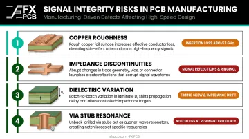
Manufacturing-Driven Signal Integrity Risks
Material properties set the performance ceiling — but manufacturing execution determines whether you reach it. Even a correctly designed board fails when fabrication introduces these problems:
- Copper roughness: Standard RO4350B uses copper roughness of 2.8 μm; the LoPro variant uses 0.6 μm. Rough copper increases insertion loss noticeably above 1 GHz and rises sharply by 10 GHz
- Impedance discontinuities: Trace width variation from inconsistent etching creates reflection points along transmission lines
- Dielectric variation: Non-uniform laminate pressing causes local Dk shifts that unpredictably alter impedance
- Via stub resonance: Undrilled via stubs create resonant cavities that attenuate specific frequency bands
Application Sectors Driving Demand
The industries requiring high frequency PCBs are expanding rapidly. The automotive radar market alone is projected to grow from USD 5.40 billion in 2023 to USD 31.45 billion by 2030 at a 29.3% CAGR, driven by ADAS adoption.
5G base stations, satellite communications, military radar, and medical imaging add further demand — and each of these sectors penalizes manufacturing shortcuts differently. That's why manufacturer selection matters as much as design.
Top High Frequency PCB Manufacturers for Signal Integrity
These manufacturers were selected based on verified capabilities in high frequency laminate processing, controlled impedance fabrication, advanced electrical testing, and demonstrated performance across demanding RF, microwave, and high-speed digital applications.
SFX PCB
SFX PCB (operating under FX PCB Co.) is a Shenzhen-based full-service manufacturer with over 15 years of experience, serving global clients in telecom, automotive, medical devices, and industrial automation. The company offers both bare PCB fabrication and full turnkey PCBA, from prototype through mass production, with a US office in Plano, TX for North American clients.
For high frequency applications, SFX PCB processes Rogers RO4003C and RO4350B laminates, PTFE (Teflon) substrates, and ceramic materials including ALN and Al2O3 — spanning sub-6 GHz through millimeter-wave applications.
The company also manufactures glass PCBs for 5G/6G base stations and radar, citing dielectric loss two to three orders of magnitude lower than silicon.
Key differentiators for signal-integrity-focused buyers:
- Free DFM analysis on every order — flags design issues before fabrication
- 100% electrical testing on every bare board
- TDR and VNA testing for impedance verification
- Laser Direct Imaging (LDI) for precise trace geometry
- IPC-A-610 Class 2/3 compliance; up to 24-layer fabrication capability
- 24-hour assembly turnaround once parts are available
| Capability | Details |
|---|---|
| Supported Materials | Rogers RO4003C, RO4350B; PTFE; ALN/Al2O3 ceramic; glass substrates |
| Frequency Coverage | Sub-6 GHz through mmWave/5G applications |
| Impedance Control | ±10% standard; TDR and VNA verification |
| Key Certifications | ISO 9001, ISO 14001, ISO 13485, IPC-A-610 Class 2/3, UL, RoHS, REACH |
| Production Scale | Prototype to mass production; up to 24 layers |
| Testing | 100% electrical, AOI, X-Ray, TDR, VNA, FCT |
North American clients can reach SFX PCB at info@sfxpcb.com or (+1) 5103455000.
TTM Technologies
TTM Technologies is one of the world's largest PCB manufacturers, headquartered in the US with facilities across North America and Asia. The company specializes in RF and microwave PCBs for defense, aerospace, telecommunications, automotive ADAS, and medical imaging, serving both high-volume OEMs and advanced prototype requirements.
TTM's RF test centers run network analyzers with sweep coverage up to 110 GHz, supporting L through W bands — from cellular infrastructure through automotive radar at 77 GHz and beyond.
The company works with over 70 resin systems, including PTFE fusion bond and hybrid dielectric constructions.
| Capability | Details |
|---|---|
| Supported Materials | 70+ resin systems; PTFE fusion bond; hybrid dielectric constructions |
| Frequency Coverage | L, S, C, X, Ku, K, Ka, V, W bands; network analyzer coverage to 110 GHz |
| Key Certifications | AS9100, IATF 16949:2016, ISO 9001:2015, ISO 13485:2016, TL 9000, NADCAP, UL |
| Process Capabilities | Sequential lamination; buried/blind vias; embedded resistors; RF connector assembly |
TTM's IATF 16949 and AS9100 certifications make it one of a small number of manufacturers qualified for both automotive radar and aerospace/defense RF programs simultaneously.
Sierra Circuits
Sierra Circuits (Sunnyvale, CA) is a US-based precision PCB manufacturer with a 70,000 sq ft facility offering in-house fabrication and assembly. The company has a dedicated RF and microwave PCB product line, with application coverage starting from 10 MHz — and fabrication turn-times as fast as one day, with turnkey assembled boards in as few as five days.
Sierra serves North American customers requiring domestic manufacture, ITAR compliance, or aerospace/medical certification. Their DFM toolset includes an impedance calculator and material selector, and they offer TDR-verified impedance control. Standard tolerance is 15%, with 10% delivered as standard and 5% achievable when specified at the design stage.
| Capability | Details |
|---|---|
| Supported Materials | PTFE and non-PTFE RF laminates; Rogers series; Isola |
| Frequency Coverage | 10 MHz and above; RF/microwave applications |
| Impedance Control | 15% standard; 10% delivered; 5% on request |
| Key Certifications | AS9100D, ISO 9001:2015, ISO 13485:2016, MIL-PRF-31032, ITAR, UL, RoHS/REACH |
| Production Scale | Standard builds up to 12 layers; advanced technology to 30 layers |
| Turn Time | Fabrication from 1 day; turnkey assembly from 5 days |
AT&S
AT&S is an Austria-headquartered PCB and IC substrate manufacturer with six production sites across Europe and Asia and approximately 13,000 employees. The company specializes in advanced HDI, embedded component technology, and substrate-like PCBs (SLP) for automotive ADAS, medical devices, and advanced industrial applications.
AT&S's differentiation lies in advanced integration rather than broad-spectrum RF laminate manufacturing. Their PCB-integrated waveguide technology targets 70 to 140 GHz and beyond, positioning the company for next-generation 5G mmWave and future 6G applications.
ECP (embedded component packaging) boards support 4 to 14 layers with embedded components 55 to 500 μm thick. SLP manufacturing uses conductor tracks of 12 to 50 μm, reducing board space by up to 30%.
| Capability | Details |
|---|---|
| Frequency Coverage | Current 5G: 26–39 GHz; integrated waveguides: 70–140 GHz and beyond |
| Advanced Technologies | PCB-integrated waveguides; embedded component packaging (ECP); SLP |
| Key Certifications | ISO 9001, IATF 16949:2016, ISO/IEC 27001:2022, EN ISO 50001:2018 |
| Production Scale | Six sites globally; ~13,000 employees; tier-1 automotive and medical OEM focus |
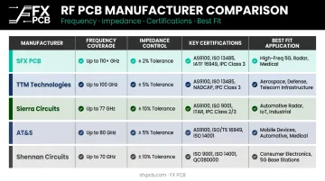
AT&S is the right fit for programs requiring advanced packaging integration, ultra-fine lines, or next-generation mmWave RF structures — not as a general-purpose RF laminate shop.
Shennan Circuits
Shennan Circuits (SNCT), founded in 1984 and headquartered in Shenzhen, is one of China's leading PCB manufacturers with particular strength in high-layer-count communication boards, server backplanes, and multilayer PCBs for 5G infrastructure. The company serves major global telecom equipment brands and has expanded into aerospace and high-end industrial applications.
Important note for buyers: Shennan's official quality page lists ISO 9001, IATF 16949, ISO 13485, AS9100, and NADCAP certificates — but visible expiration dates on ISO 9001 and IATF 16949 show May 22, 2026, and ISO 13485 expired October 23, 2025. Buyers should request current certificate documentation directly before qualifying Shennan for regulated programs.
| Capability | Details |
|---|---|
| Core Strength | High-layer-count multilayer PCBs; communication backplanes; 5G infrastructure |
| Listed Certifications | ISO 9001, IATF 16949, AS9100, ISO 13485, NADCAP, QC080000 (verify currency) |
| Market Focus | Global telecom OEMs; 5G base station supply chain |
| Frequency/Materials | Confirm directly — not publicly verified for mmWave laminate specifics |
What to Look for in a High Frequency PCB Manufacturer
Material Qualification and Handling
A capable HF PCB manufacturer actively qualifies incoming laminate batches — verifying Dk and Df values against certificate of conformance (COC) documentation. PTFE and ceramic-filled substrates require controlled storage to prevent moisture absorption that shifts electrical properties during fabrication. Ask directly about incoming inspection protocols and storage conditions; uncontrolled storage is where batch-to-batch performance variation most often originates.
Impedance Control Precision
High frequency designs demand tighter tolerances than commodity PCB manufacturing provides. What to ask:
- What is your documented impedance control tolerance? (±10% is standard; ±5% is achievable at manufacturers like Sierra)
- How do you verify it? TDR coupons on every production panel is the gold standard
- Do you use Laser Direct Imaging (LDI) for trace patterning?
SFX PCB uses LDI and offers TDR/VNA verification. Sierra achieves ±5% when specified at design stage. TTM's 110 GHz network analyzer coverage supports validation at operating frequency, not just at DC.
Testing and Validation Infrastructure
The testing stack that separates capable HF manufacturers from commodity shops:
| Test Method | What It Verifies |
|---|---|
| 100% electrical testing | Continuity and isolation on every bare board |
| AOI | Trace geometry, copper coverage, via placement |
| TDR | Impedance profile along transmission lines; detects discontinuities |
| VNA sweeps | Insertion loss, return loss at actual operating frequencies |
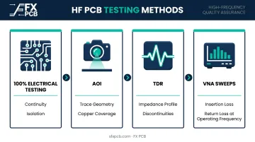
Any manufacturer working on boards above 5 GHz should offer TDR and AOI as standard, not optional add-ons.
Certifications and Traceability
Match certifications to your end application:
- ISO 9001 — baseline quality management (required for all)
- IPC-A-610 Class 2/3 — assembly acceptance criteria
- AS9100D — aerospace and defense
- IATF 16949 — automotive ADAS and radar
- ISO 13485 — medical devices
- MIL-PRF-31032 — military PCB performance
Request batch-level traceability records and verify certificate expiration dates — not just a logo on a website.
DFM Support and Engineering Collaboration
Problems caught before fabrication cost far less than rework. Free DFM analysis — like SFX PCB provides on every order — flags impedance discontinuities, via stub risks, and stackup asymmetries before a single board is built.
Frequently Asked Questions
Which type of PCB is used for high frequency applications?
High frequency applications use boards built on low-Dk, low-Df laminates such as Rogers (RO4350B, RO4003C), PTFE/Teflon, polyimide, or ceramic-filled composites. Standard FR4 exhibits high dielectric loss and unstable Dk above a few hundred MHz, making it unsuitable for RF and microwave applications.
Which technique is commonly used in high-speed PCB design to minimize signal integrity issues?
Several techniques work in combination: controlled impedance routing (microstrip or stripline), differential pair routing, via stub back-drilling, the 3W rule for trace spacing, and solid reference planes. Together, they suppress reflections, crosstalk, and insertion loss across frequency.
What is the 20H rule in PCB design?
The 20H rule recommends pulling back the power plane by a distance equal to 20 times the dielectric thickness between power and ground planes. This ensures fringing electric fields at board edges are absorbed by the ground plane rather than radiated externally, reducing EMI and plane-to-plane coupling.
What materials are best for high frequency PCB manufacturing?
Rogers RO4350B (Dk 3.48, Df 0.0037 at 10 GHz) suits 500 MHz to 3 GHz and beyond, while PTFE and polyimide handle higher frequencies with very low loss tangents. Material selection depends on target frequency, thermal requirements, and cost, since no single substrate performs optimally across all applications.
How do manufacturers test high frequency PCBs for signal integrity?
Primary methods include TDR to measure impedance and detect discontinuities, and VNA sweeps to characterize insertion and return loss at operating frequencies. AOI verifies trace geometry, while 100% electrical continuity testing covers every bare board.
What certifications should a high frequency PCB manufacturer have?
ISO 9001, IPC-A-610 Class 2 or 3, and UL are baseline requirements. For regulated applications, industry-specific credentials are non-negotiable: ISO 13485 for medical, AS9100D for aerospace/defense, and IATF 16949 for automotive. Request current certificates and batch-level traceability records before committing to a supplier.
Conclusion
For high frequency PCB applications, manufacturing quality is inseparable from signal performance. Laminate handling, etch precision, via control, and testing rigor determine whether a board meets spec — the schematic alone doesn't.
Evaluate manufacturers on impedance yield data, first-pass success rates, DFM collaboration depth, and certification currency relative to your industry. A lower quote from a shop without verified HF laminate experience typically costs far more in rework, delays, and field failures than the initial savings suggest.
If you're applying those criteria and need a manufacturer that checks every box, SFX PCB is worth a direct conversation. Key credentials:
- 15+ years of PCB and PCBA manufacturing experience
- IPC-A-610 Class 2/3 production standards
- Free DFM analysis on every order
- Prototype-to-production scaling without switching suppliers
- Dedicated US office in Plano, TX for North American support
Reach out at info@sfxpcb.com or (+1) 510-345-5000 to discuss your next high frequency project.