Unlike standard FR4 boards, RF microwave PCBs carry a cost range that spans more than an order of magnitude per square inch. That range is driven by substrate material, layer count, fabrication tolerances, and order volume — and misreading it in either direction creates problems. Over-specify the material and you burn budget on performance your design never uses. Under-specify it and you face a redesign cycle that costs far more than the premium material would have.
This guide breaks down the real per-square-inch cost tiers, the factors that drive them, and how to budget accurately before you go out for quotes.
Key Takeaways
- FR4-based RF boards start under $1/sq inch; Rogers RO4000 series runs $5–$20/sq inch; premium PTFE laminates can exceed $20/sq inch
- Substrate material is the single biggest cost driver — Rogers and PTFE laminates cost 3–10x more than FR4 per square inch
- Per-unit costs drop sharply at production volumes — prototype runs (5–50 boards) carry NRE fees and poor panel utilization that inflate cost
- Hybrid stackups (PTFE/Rogers signal layers + FR4 ground planes) can cut total material costs by up to 30% while maintaining RF performance
RF Microwave PCB Cost Per Square Inch: Pricing Overview
RF microwave PCBs have no single fixed price — costs range from a few cents per square inch for simple FR4 configurations to well over $20 for exotic PTFE laminates. Choosing the wrong tier creates downstream costs: a budget FR4 build at 5 GHz produces unacceptable insertion loss; a full RT/Duroid stack for a sub-1GHz IoT module wastes several hundred dollars per board.
Three practical tiers cover the full spectrum. Each is summarized below based on fabricator-reported 2025 benchmarks. Note that pricing sources use different area units (cm², m², sq ft) — where possible, figures are provided as published to preserve accuracy.
Budget Tier: FR4-Based RF Boards
Fabricated cost range: ~$0.50–$1.20/cm² for FR4 hybrid RF stackups (KingSun 2025 pricing data; pure FR4 RF pricing varies by layer count and volume).
What's included at this tier:
- Standard or high-Tg FR4 substrates
- 2-layer configurations most common
- HASL or OSP surface finishes
- Suitable for RF applications up to roughly 1 GHz
Best for: IoT wireless modules, low-frequency consumer RF electronics, cost-sensitive prototypes where signal loss at higher frequencies is not a concern.
Mid-Grade Tier: Rogers RO4000 Series
Typical fabricated cost: $1.50–$2.80/cm² for RO4350B; 2-layer RO4003C runs approximately $180–$250/m² at small quantities, dropping to $90–$120/m² at 100+ pieces (KingSun Rogers 4003 Price Guide, 2025).
What's included:
- Rogers RO4003C (Dk 3.38 ±0.05, Df 0.0027 at 10 GHz) or RO4350B (Dk 3.48 ±0.05, Df 0.0037 at 10 GHz)
- Compatible with standard FR4 manufacturing processes — this keeps fabrication cost meaningfully lower than pure PTFE
- Strong Dk stability across temperature and frequency ranges
Best for: Cellular antennas, automotive radar, 5G sub-6GHz components, RFID readers, and any application requiring reliable impedance control above 1 GHz.
Premium Tier: PTFE, RT/Duroid, and Exotic Laminates
Typical fabricated cost: $4.50–$5.00/cm² for full PTFE builds; Rogers RT/duroid 5880 raw material runs approximately $20/sq ft, with fabricated boards reflecting significant process cost premiums (KingSun RT/duroid 5880 Cost data, 2025).
What's included:
- Pure PTFE or ceramic-filled PTFE composites
- RT/duroid 5880 specs: Dk 2.20 ±0.02, Df 0.0009 at 10 GHz (3× lower dissipation than RO4003C)
- Requires specialized drilling, plasma or sodium etch for copper adhesion, and cleanroom handling
Best for: Military radar, satellite communications, mmWave 5G, aerospace navigation — any application where signal loss directly degrades system performance.
Key Factors That Drive RF Microwave PCB Costs
RF microwave PCB pricing reflects a combination of material science, fabrication complexity, and production economics. Understanding each factor lets you make targeted trade-offs.
Substrate Material and Dielectric Properties
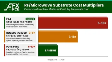
Laminate choice is the dominant cost driver. PTFE and ceramic-filled variants require specialized raw materials — KingSun reports PTFE raw stock at $50–$100/sq ft versus $15–$30/sq ft for Rogers RO4350B and $2.50–$5.00/sq ft for FR4. Fabrication costs amplify that material gap:
- FR4 to Rogers RO4000: 3–5x cost multiplier per square inch
- FR4 to pure PTFE: 5–10x cost multiplier
- Additional processes for PTFE: plasma etching, specialized drill speeds, higher scrap rates
The dissipation factor (Df) is what justifies this premium. At 10 GHz, FR4's Df runs 4x higher than RO4003C — signal loss that becomes unacceptable in radar, mmWave, or satellite applications.
Layer Count and Stackup Complexity
Adding layers to an RF board does not increase cost linearly. Each new layer requires additional lamination cycles, vacuum pressing, and inner-layer registration precision.
| Configuration | Approximate Cost Premium |
|---|---|
| 2-layer to 4-layer RF board | +30–40% overall |
| Each additional layer adder | +15–25% per layer |
A 4-layer Rogers RO4003C board at low volume runs $280–$400/m², compared to $180–$250/m² for a 2-layer equivalent (KingSun 2025 data).
Precision Drilling, Via Types, and Impedance Control
PTFE's softness creates via defects at standard drill speeds — requiring slower feeds, specialized bits, and higher scrap rates. For RF boards with microvias:
- Laser-drilled microvias: $5–$20 per board additional cost
- Blind/buried via complexity: $10–$50 per board additional
- Laser drilling order adder on RO4003C: $60–$100 per order (KingSun 2025)
Tight impedance tolerances (±5% or better) also require TDR verification and impedance test coupons. For reference, SFX PCB delivers impedance-controlled fabrication at ±10% tolerance as standard, with tighter tolerances available for critical RF applications.
Surface Finish Selection
ENIG is the preferred finish for RF boards — its flat surface minimizes impedance variation and its oxidation resistance preserves signal integrity during storage and assembly. Cost impact per panel:
- HASL: $5–$15 per panel (baseline)
- ENIG: $25–$50 per panel (adds $16–$25/m² on Rogers boards)
- Immersion Silver: moderate cost position, used in some high-frequency designs for superior electrical properties
Order Volume and Panelization Efficiency
Prototype quantities carry disproportionately high per-unit costs. NRE fees, setup charges, and low panel utilization all front-load the cost.
| Quantity | 2-Layer RO4003C (100x100mm) | Cost Driver |
|---|---|---|
| Small qty (prototype) | $180–$250/m² | Setup, NRE, low utilization |
| 100+ pieces | $90–$120/m² | Amortized setup, better panel fill |
| 4-layer, small qty | $280–$400/m² | Additional lamination complexity |
| 4-layer, 100+ pieces | $160–$220/m² | Volume efficiency |
(KingSun Rogers 4003 Price Guide, 2025)
Material-by-Material Cost Per Square Inch Comparison
Material selection is the fastest lever for changing your RF PCB cost — and the most consequential decision for signal performance. The table below consolidates verified specs and fabricator-reported pricing benchmarks.
| Material | Approx. Cost/cm² | Dk | Df (10 GHz) | Max Practical Freq. | Best Application |
|---|---|---|---|---|---|
| FR4 RF / hybrid | $0.50–$1.20 | ~4.5 (varies by grade) | ~0.020 (typical) | ~1 GHz | Budget RF, IoT, prototypes |
| Rogers RO4003C | ~$1.80–$2.50 | 3.38 ±0.05 | 0.0027 | 10–30 GHz | Cost-sensitive RF/microwave |
| Rogers RO4350B | $1.50–$2.80 | 3.48 ±0.05 | 0.0037 | 10–30 GHz | High-volume RF power designs |
| Full PTFE (Rogers RT/duroid 5880) | $4.50–$5.00+ | 2.20 ±0.02 | 0.0009 | 40 GHz+ | Radar, satellite, mmWave |
| Rogers RT/duroid 6002 | Premium pricing | 2.94 ±0.04 | 0.0012 | 30–40 GHz+ | Aerospace multilayer designs |
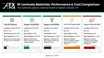
Note: Pricing reflects fabricator-reported benchmarks (KingSun 2025); actual quotes depend on layer count, volume, board size, and specific build configuration.
FR4 for RF: When It Works and When It Doesn't
FR4 is viable for RF below approximately 1 GHz. Above that threshold, its dissipation factor — roughly 4x higher than RO4003C at microwave frequencies — causes signal loss that compounds across transmission line length. The low cost per square inch makes FR4 appealing for budget prototypes, but applying it at 5 GHz almost guarantees a redesign. The cost of that redesign typically exceeds what the Rogers upgrade would have cost at prototype stage.
Rogers RO4000 Series: The Balanced Option
RO4003C and RO4350B offer strong Dk stability and dramatically lower loss than FR4, while using FR4-compatible manufacturing processes. That process compatibility keeps fabrication cost manageable, which is why these materials sit in the mid-grade tier rather than the premium tier. One important nuance flagged by Microwaves101: the RO4000 family includes multiple variants, and not all offer a meaningful Df advantage over FR4. RO4003C at 0.0027 Df clearly does; buyers should verify the specific variant rather than assuming all RO4000 materials perform equivalently.
PTFE and RT/Duroid: When Premium Is Necessary
PTFE-based laminates are specified for military radar, space payloads, and mmWave systems where signal integrity requirements leave no margin for material compromise. Their ultra-low Df (0.0009 for RT/duroid 5880) and stable Dk across wide temperature ranges meet performance thresholds that RO4000-series materials cannot reach.
The cost premium comes less from raw material than from fabrication complexity:
- PTFE's non-stick surface requires specialized adhesion processes
- Its softness demands slower drill speeds to prevent delamination
- Contamination sensitivity requires controlled handling throughout production
Hybrid Stackups: A Cost Optimization Strategy
Given the fabrication overhead of full PTFE builds, hybrid stackups offer a practical middle ground. The approach places Rogers or PTFE material only on the RF signal layers, while FR4 or standard RO4000 material handles ground planes and power distribution. KingSun's 2025 data indicates hybrid Rogers/FR4 configurations can reduce total board material cost by up to 30% compared to a full high-frequency laminate stack, while maintaining equivalent electrical performance on critical signal layers. Sierra Circuits confirms the approach is most cost-effective when a single prepreg type bonds the hybrid cores, using materials like Rogers 4350 paired with 370HR cores. SFX PCB supports hybrid stackup configurations combining Rogers and PTFE layers with standard substrates.
Hidden RF PCB Cost Components Most Buyers Overlook
NRE and Engineering Setup Fees
New RF PCB designs typically incur one-time setup charges that most buyers don't account for at the budgeting stage:
- RF PCB NRE/tooling/setup: $50–$100 per new design
- Controlled impedance setup: $20–$35 plus $5/m²
- RO4003C NRE/tooling: $30–$80 per design
At prototype quantities of 5–10 boards, these fees can add $5–$20 per unit to the apparent per-board cost. Factor them in before comparing quotes.
Specialized Testing Requirements
Aerospace and defense RF boards require electrical testing that standard PCBs skip:
- Impedance testing: $20–$50 per order
- TDR verification, insertion loss, RF functional testing: per-board costs vary by test complexity; budget these as separate line items when quoting high-reliability designs
IPC-6012 Class 3 (required for space and military avionics) demands stricter annular ring requirements and hole-to-pad registration than Class 2, which increases fabrication cost accordingly.
SFX PCB holds IPC-A-610 Class 2/3 certification and performs 100% electrical testing on every bare board as standard practice.
Regional Cost Differences and Lead Time Trade-offs
Shenzhen-based fabrication offers lower unit costs for RF microwave PCBs. KingSun's 2025 regional data for a 100x100mm 2-layer RO4003C prototype illustrates the spread:
| Region | Approx. Per-Piece Cost | Lead Time |
|---|---|---|
| China (Shenzhen) | $14–$20 | 5–7 days |
| United States | $28–$45 | 7–14 days |
| Europe | $32–$50 | 10–15 days |
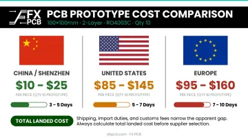
Buyers should account for shipping, import duties, and lead time when calculating total landed cost — the unit price gap narrows once these are included. SFX PCB, with 15+ years of RF PCB experience, ISO-certified Shenzhen facilities, and a US office in Plano, Texas, delivers on quality standards while keeping the pricing advantage of direct Chinese fabrication.
How to Estimate the Right RF PCB Budget
Key Decision Variables Before Quoting
Define these before approaching any fabricator:
- Target frequency range — determines whether FR4, RO4000, or PTFE is even viable
- Required impedance tolerance — ±10% vs. ±5% affects both process choice and testing cost
- Operating temperature range — stable Dk over temperature is a PTFE/Rogers advantage FR4 cannot match
- Production volume — prototype NRE dominates at low quantities; production pricing at 500+ units looks very different
- Certification requirements — IPC-6012 Class 2 vs. Class 3, ISO13485 for medical, RoHS/REACH for EU market access
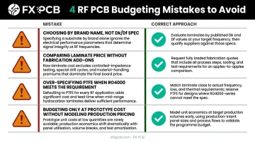
Each variable pushes the cost per square inch into a specific tier. Locking these down before quoting also shapes which of the four budgeting mistakes below you're most likely to hit.
Common Budgeting Mistakes to Avoid
Four errors appear consistently in RF PCB budgeting:
- Choosing substrate by brand name rather than required Dk/Df specification — below 1 GHz, several Rogers materials offer no measurable advantage over FR4
- Comparing laminate prices without fabrication add-ons — specialized drilling, impedance testing, and ENIG finish costs must be included
- Over-specifying PTFE for applications RO4000 would serve — a $4.50/cm² full PTFE build when $2/cm² RO4350B meets the spec wastes real money
- Budgeting only at prototype cost without modeling production pricing — per-unit cost at 500 units can be 40–70% lower than at 10 units
How DFM Analysis Reduces Cost Before Fabrication
A Design for Manufacturability (DFM) review catches cost-driving design decisions before a single board is built. SFX PCB includes free DFM analysis on every order, covering stackup choices, via structures, trace geometry, and material selection against your actual electrical requirements.
For RF boards specifically, DFM review can identify:
- Opportunities to reduce layer count without compromising shielding or routing
- Material substitutions where a lower-cost laminate meets the actual Dk/Df spec
- Via structure simplifications that eliminate microvia complexity
- Surface finish selections optimized for the specific frequency range
This analysis is particularly valuable for engineers new to RF PCB design who default to over-specified materials. The savings on material and fabrication complexity add up quickly, especially when a single DFM catch prevents a redesign cycle that costs ten times the original board price.
Frequently Asked Questions
What is the cost of a PCB board?
Standard FR4 PCBs range from roughly $0.20 to $50 per board depending on size, layer count, and volume. RF microwave PCBs cost significantly more due to premium substrates and tighter fabrication tolerances, which is why cost per square inch is a more useful comparison metric than per-piece pricing for RF applications.
What is the typical cost per square inch for an RF microwave PCB?
FR4-based RF boards start under $1/sq inch; Rogers RO4000 series boards typically fall in the $1.50–$2.80/sq inch range; premium PTFE/RT Duroid boards reach $4.50–$5.00/sq inch or more depending on configuration and volume. Layer count and quantity significantly affect where within each tier you land.
Why is Rogers PCB more expensive than FR4?
Rogers materials use engineered laminates with tightly controlled dielectric constants and dissipation factors, which demand more expensive raw materials and specialized fabrication. The result is 3–8x higher cost per square inch than FR4 — necessary for reliable performance above 1 GHz where FR4 signal loss becomes unacceptable.
Can FR4 be used for RF and microwave applications?
FR4 is viable for RF designs operating below approximately 1 GHz. Above that, its relatively high dissipation factor causes signal loss that degrades system performance — making Rogers or PTFE materials necessary for reliable microwave-frequency operation.
How does production volume affect RF microwave PCB pricing?
Prototype quantities (5–50 boards) carry high per-unit costs from NRE fees and low panel utilization. At 500+ boards, per-unit cost drops 40–70% as setup costs spread across the run — a critical variable in total program budgeting.
What is a hybrid stackup and can it reduce RF PCB costs?
A hybrid stackup uses premium RF laminates only on signal-critical layers and lower-cost FR4 or RO4000 on ground and power layers. This approach can reduce total material costs by up to 30% compared to an all-PTFE or all-Rogers stack while preserving the signal integrity properties the design requires.