Introduction
Industrial PCBs sit underneath almost every piece of equipment running a modern factory floor — from PLC controllers and servo drives to medical imaging systems and power distribution units. Get the selection wrong and the consequences follow quickly: field failures, unplanned downtime, costly recalls, and compliance exposure.
The challenge is that "industrial PCB" isn't a single product. It's a spectrum of constructions, materials, and quality classes — each matched to specific electrical demands, thermal environments, and service life targets.
This guide covers the main industrial PCB types — rigid multilayer, metal-core, rigid-flex, and more — how each performs under real operating conditions, and the selection factors that matter most when you're writing a specification.
Key Takeaways
- FR-4 rigid boards dominate the market but aren't suitable for every industrial environment
- Multilayer PCBs are the standard for PLCs, motor drives, and any design requiring EMI immunity or controlled impedance
- Flex and rigid-flex designs eliminate vulnerable cable harnesses in dynamic mechanical environments
- Metal core, thick copper, HDI, and high-frequency boards each address a specific thermal, density, or RF constraint
- PCB type selection should follow a structured review — not habit or default
What Is an Industrial PCB?
An industrial PCB is a printed circuit board engineered to function reliably under conditions that would degrade or destroy a consumer-grade board: elevated operating temperatures, mechanical vibration, electrical noise, humidity exposure, and multi-year service life expectations.
Meeting those demands starts with the right classification. The "industrial" designation covers both the end-use sector — automation, energy, defense, medical — and the design standards the board must meet. Two quality tiers define the baseline:
- IPC-A-610 Class 2 — For dedicated-service electronics where extended life is needed but uninterrupted operation isn't always critical. Applies to most general industrial equipment.
- IPC-A-610 Class 3 — For high-performance or life-critical applications where downtime cannot be tolerated. Mandates tighter manufacturing tolerances, more extensive inspection, and stricter acceptance criteria. Common in aerospace, defense, and medical devices.
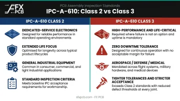
Choosing between Class 2 and Class 3 is just the starting point. From there, electrical complexity, thermal demands, and physical constraints determine which PCB format fits — and the rest of this guide breaks each one down.
Types of Industrial PCBs
Industrial PCBs are classified along three dimensions: layer count, physical form factor (rigid vs. flexible), and specialized material or construction. Different applications call for different combinations.
Rigid Single-Layer and Double-Layer PCBs
The most widely manufactured PCB format globally uses FR-4 (woven fiberglass and epoxy resin) as its substrate. Single-layer versions carry copper traces on one side; double-layer boards run traces on both sides connected by through-holes.
FR-4 glass epoxy held over 52% of PCB substrate material revenue in 2025, which reflects just how dominant this construction remains. Standard FR-4 grades carry a glass transition temperature (Tg) of around 130–140°C. For higher-temperature industrial environments, high-Tg FR-4 variants push this to 180°C with improved thermal margin.
Best suited for: Sensor interface boards, relay panels, LED driver circuits, industrial HMI display boards, and straightforward power supply boards where design complexity is low-to-moderate.
Limitations to know:
- No ground plane on single-layer boards — EMI vulnerability in electrically noisy environments
- Limited routing density rules out miniaturized or complex circuit designs
- No inherent thermal management advantage for power-intensive loads
SFX PCB's standard rigid FR-4 boards support Tg130 through Tg180 options, outer layer copper from 18µm to 350µm (0.5 oz to 10 oz), and board thickness from 0.1mm to 8mm — covering most industrial single and double-layer requirements.
Multilayer PCBs
Multilayer boards stack four or more copper layers (alternating signal, ground, and power planes) laminated into a single rigid structure.
The internal ground and power planes are the defining feature: they provide controlled signal return paths, EMI shielding, and dedicated power delivery that aren't available in two-layer designs.
IEEE research confirms that split or disrupted reference planes in high-speed designs break return-current paths, causing signal distortion, crosstalk, and radiated emissions. Internal ground planes in multilayer boards prevent this by maintaining continuous, low-impedance return paths for every signal layer.
Best suited for: Industrial PLCs, motor drives, data acquisition systems, robotics controllers, medical diagnostic equipment, and any design requiring high-speed signal processing, dense component placement, or strong EMI immunity.
Key strengths:
- Controlled impedance routing for high-frequency signals
- Internal power planes stabilize voltage delivery to microprocessors and FPGAs
- Higher component density in a smaller footprint than equivalent two-layer designs
- Significantly reduced EMI susceptibility compared to single or double-layer boards
Limitations: Higher fabrication cost and longer lead times than simple rigid boards. Inner layer defects found after lamination can't be reworked — you scrap the board. Design complexity requires thorough DFM review before committing to production.
SFX PCB supports multilayer rigid PCBs from 4 layers up to 68 layers, with controlled impedance stackups held to ±10% tolerance as a standard service.
Flex and Rigid-Flex PCBs
Flex PCBs use polyimide substrates (such as DuPont Kapton) that allow the board to bend, fold, or wrap around mechanical structures while maintaining full electrical continuity. Kapton retains useful properties across -269°C to 400°C and resists all known organic solvents, making it chemically resilient in demanding industrial environments.
Rigid-flex boards combine rigid sections (for component mounting) with flexible interconnect sections in a single integrated structure. This eliminates the separate connectors and ribbon cables between rigid boards that commonly fail in high-vibration industrial environments.
The flexible PCB market reached $23.89 billion in 2024 and is projected to hit $50.90 billion by 2030 at 13.7% CAGR, driven by growing demand across robotics, medical devices, and aerospace.
Best suited for: Industrial robotics joints requiring dynamic flexing, wearable industrial sensors, compact medical devices (endoscopes, imaging equipment), aerospace electronics, and any application where the board must route around mechanical obstacles or replace a cable harness assembly.
Key strengths:
- Eliminates mechanical connectors — a primary source of field failures in high-vibration environments
- Flex assemblies can occupy roughly 10% of the volume of equivalent rigid multi-board assemblies
- Polyimide substrate offers thermal stability and chemical resistance well beyond FR-4
Limitations: Significantly higher fabrication cost than rigid boards. Bend radius, layer transitions, and strain relief zones require specialized design expertise. Not cost-justified where a rigid board with standard connectors would work adequately.
SFX PCB distinguishes between dynamic flex (designed for continuous flexing, rated for 100+ flex cycles) and flex-to-install designs (bent once during assembly), handling each with different edge-reinforcement approaches.
Specialized Industrial PCB Formats
Four additional formats address specific performance constraints that standard rigid and flex constructions can't meet:
| Format | Core Advantage | Common Applications |
|---|---|---|
| Metal Core / Aluminum PCB | Superior heat dissipation — aluminum substrate conducts heat far faster than FR-4's ~0.3–0.4 W/mK | High-power LED lighting, power electronics, motor control, automotive |
| Thick Copper PCB | Handles high current loads — defined as ≥3 oz copper per layer | Power distribution, industrial inverters, EV charging equipment |
| HDI PCB | Higher component density via microvias ≤150µm — roughly 1/10 the inductance of standard through-holes | Compact industrial computers, telecom equipment, advanced medical devices |
| High-Frequency PCB | Rogers RO4003C achieves Dk 3.38 ±0.05 at 10 GHz vs FR-4's ~4.5 — critical for signal integrity at GHz frequencies | Industrial radar, wireless infrastructure, RF sensing systems |
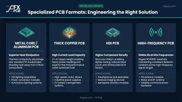
SFX PCB fabricates all four formats. Aluminum PCBs are available up to 1200mm x 480mm with 1 oz to 10 oz copper options. Thick copper boards support up to 20 oz copper weight. HDI builds use laser-drilled microvias down to 0.10mm (4 mil) diameter. High-frequency boards are available in Rogers RO4003C and RO4350B grades, as well as PTFE (Teflon) substrates.
Important: not every industrial application requires a specialty substrate. Over-specifying adds cost without measurable benefit. Choose specialty formats only when a specific electrical or thermal threshold genuinely demands it.
How to Choose the Right Industrial PCB
The right PCB type follows from technical requirements, operating environment, and production constraints — not from what's most commonly used or most technologically advanced.
Electrical Complexity and Routing Density
Evaluate signal net count, component density, operating frequencies, and impedance control requirements. A simple sensor interface board may work perfectly on double-layer FR-4. A complex motor drive or embedded computer requires multilayer construction.
SFX PCB's free DFM analysis — included with every order — can identify whether a design genuinely needs additional layers or whether routing optimization could reduce layer count and cost.
Thermal and Power Demands
Standard FR-4 copper weight baseline is 1 oz/ft² (35µm). Once power demands or heat concentration exceed what standard construction handles, the substrate choice becomes critical:
- Thick copper construction: required when copper weight exceeds 3 oz/ft²
- Metal core substrates: suited for concentrated heat sources — high-power LEDs, power MOSFETs, motor control ICs
- Thermal conductivity: determines whether the board maintains acceptable junction temperatures at rated power
Mechanical Environment and Physical Constraints
Consider whether the board will face continuous vibration, shock loads, repeated flex cycles, or must fit within a non-planar housing. A 2022 peer-reviewed study demonstrated that increasing PCB thickness from 1.0mm to 1.6mm raised mean time to failure under vibration from 137 hours to 540 hours — mechanical design decisions directly affect field reliability. If dynamic flexing is required, rigid PCBs alone will cause fatigue fractures. Rigid-flex or flex construction becomes the correct choice.

Reliability Class and Compliance Requirements
Pin down which IPC-A-610 quality class applies before finalizing the specification. Class 2 covers most general industrial equipment; Class 3 applies to continuous-service and life-critical applications. The required class directly affects manufacturing tolerances, inspection criteria, and acceptable defect conditions. SFX PCB holds IPC-A-610 Class 2/3 certification, covering both tiers.
Volume, Budget, and Timeline
A technically superior PCB type is only the right choice if it can be manufactured within acceptable cost and timeline constraints. Multilayer, flex, and specialty substrate boards carry higher per-unit cost and longer fabrication lead times than simple rigid boards.
For high-volume industrial production, the unit cost difference between a 4-layer and 6-layer board often becomes irrelevant compared to the cost of a single field failure. Metal core prototype lead times at SFX PCB run 5–16 working days depending on construction; production quantities add a few days beyond that.
What to Check Before Finalizing Your Industrial PCB Specification
Mistake 1: Over-specifying without analysis
Many engineers default to higher-complexity PCB types out of caution rather than validated need. This inflates unit cost and lead time without delivering measurable reliability improvement. Confirm layer count through a stackup analysis before finalizing. DFM review confirms whether your design requires 6 layers or whether routing optimization achieves the same result on 4.
Mistake 2: Selecting by familiarity instead of fit
Teams that always use multilayer boards apply them to simple control circuits where double-layer would suffice. Teams unfamiliar with rigid-flex keep using rigid boards with cable harnesses in vibrating environments, and the field failures follow.
PCB type selection needs a structured review of the application's requirements. SFX PCB's IPC-A-610 Class 2/3 certified manufacturing and 100% electrical testing on every bare board provide a quality backstop, but the right type has to be specified upfront.
Mistake 3: Ignoring total cost of ownership
A cheaper PCB to fabricate can be far more expensive over the product's lifecycle if it fails sooner, requires more frequent replacement, or can't accommodate design revisions without a complete redesign. Neither multilayer nor rigid-flex boards can be repaired at the board level. That constraint must factor into total cost of ownership calculations for industrial equipment with multi-year service requirements.
Key TCO factors to evaluate before committing to a board type:
- Repairability: Can technicians replace individual components, or does any failure require full board swap?
- Revision tolerance: Will a design change require a complete re-stackup or just a layer re-route?
- Replacement frequency: How does MTBF compare across board types under your operating conditions?
- Lifecycle cost: Does the lower fabrication cost offset increased field support or downtime risk?
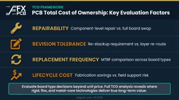
SFX PCB's engineering consultation service can help evaluate these trade-offs before production commitment.
Frequently Asked Questions
What is an industrial PCB?
An industrial PCB is a printed circuit board designed to operate reliably in demanding conditions — elevated temperatures, vibration, electrical noise, and extended service lifecycles. These boards are manufactured to higher quality standards than consumer-grade products, typically IPC-A-610 Class 2 or Class 3, depending on the application's reliability requirements.
What are the main types of PCBs used in industrial applications?
Industrial PCBs are classified by layer count (single-layer, double-layer, multilayer), physical form factor (rigid, flex, rigid-flex), and specialized construction (metal core, HDI, high-frequency, thick copper). Most industrial applications require multilayer, flex, or specialty formats rather than simple single or double-layer rigid boards.
Are industrial PCBs made from FR-4?
FR-4 is the most common substrate, holding over 52% of PCB substrate material revenue in 2025. However, industrial applications often require alternatives: polyimide for flex boards, aluminum or copper core for thermal management, or Rogers-grade PTFE laminates for high-frequency RF circuits.
What PCB type is best for industrial automation applications?
Most PLCs, motion controllers, and servo drives use multilayer rigid PCBs — typically 4 to 8 layers — for their EMI immunity, signal integrity, and routing density. Robotic joints and mobile automation platforms increasingly rely on rigid-flex PCBs to eliminate cable harnesses that fail under repeated vibration and flexing cycles.
What is the difference between IPC Class 2 and Class 3 for industrial PCBs?
Class 2 applies to general industrial equipment where high performance is required but failure isn't immediately life-threatening. Class 3 applies to continuous-service or life-critical systems — aerospace, defense, medical — where any functional failure is unacceptable. It mandates tighter manufacturing tolerances, more extensive inspection, and stricter acceptance criteria at every stage.
How do I know if I need a multilayer PCB for my industrial project?
Multilayer construction is warranted when component density can't be routed on two layers, operating frequencies require controlled impedance, or EMI immunity via internal ground planes is needed. A DFM (Design for Manufacturability) analysis — offered free with every FX PCB order — is the fastest way to confirm whether a 2-layer design works or a multilayer board is truly needed.